Introduction
This guide demonstrates 3D modeling techniques for creating functional jigs & fixtures. This is a slightly more advanced article, with an assumption of some experience using 3D modeling programs.
3D printing will allow this part to be created quickly, reducing lead times during manufacturing and reducing costs of tooling. Complex and bespoke tool geometries can be created easily and cost effectively, without the constraints of tradional manufacturing.
Fusion 360 has been used to model these parts but most CAD packages are very similar in operation. If you don’t currently have Fusion you can download a free copy for hobbyist use here.
This part is both a jig & fixture; it clamps a pneumatic wheel and has guides for drilling holes through the spokes of the wheel which will be used to mount a pulley. The design includes drill bushes that align the drill bit when drilling for accurate and perpendicular holes that do not damage the jig.
 Showing assembly of the jig & fixture assembly.
 Section view of the completed jig & fixture.
Part 1 - Importing Geometry
It is beneficial to have a 3D model of the part that the jig or fixture is to be used with. This enables an accurate and dimensionally compatible result. The wheel was created first using basic modeling techniques including Extrude, Revolve & Fillet features. It is also possible to download an existing model from websites such as GrabCad, however it is important to verify the dimensions are correct before parts are produced.
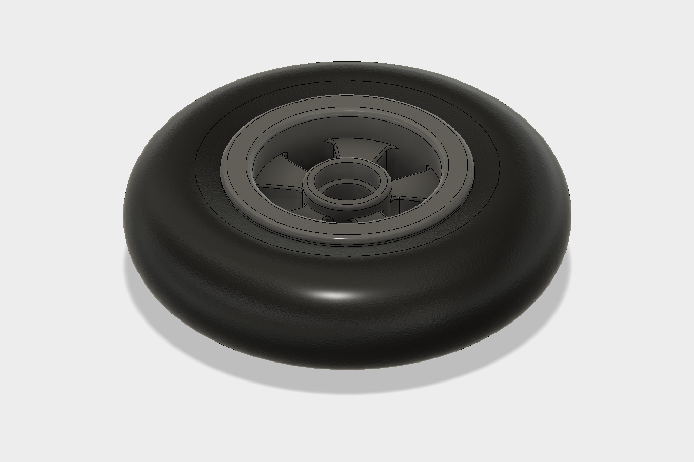 Wheel that will be used as the basis for the jig & fixture.
The wheel was then imported into a new file by selecting ‘Insert into Current Design’ in the right click menu from the file browser. This workflow enables any changes to the original wheel to be linked to the Jig & Fixture part, resulting in any updates to the wheel being reflected in the part.
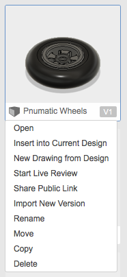
Right click menu in file browser.
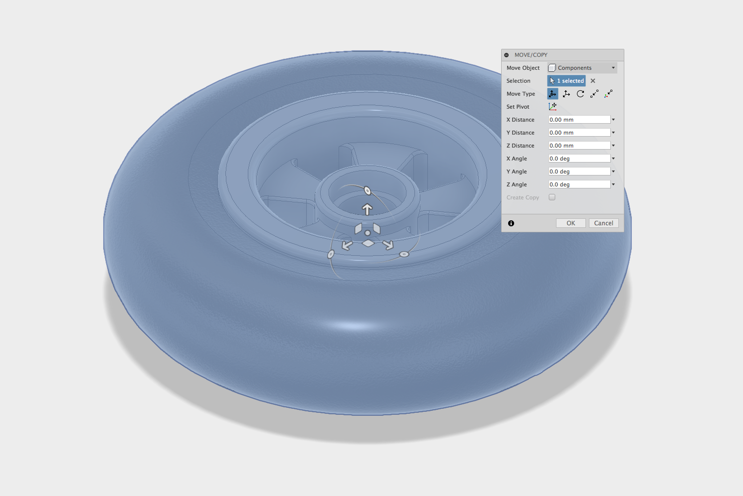 Wheel inserted into new file.
The wheel can be placed anywhere in the file, however it is good practise to place the part centrally to the origin which will make later operations much easier. The workpiece geometry which will be used for the basis of the Jig & Fixture is now setup.
Part 2 - Fixture Body
The fixture will clamp the wheel hub in position and align the spokes of the wheel while drilling. Because the part is symmetrical, the top half will be modeled and then mirrored to create the second half of the fixture.
The first sketch can be created on the top surface of the wheel hub which will be used to create the main body of the fixture. The Combine tool will be used later to cut away material for the spokes so it can be clamped together.
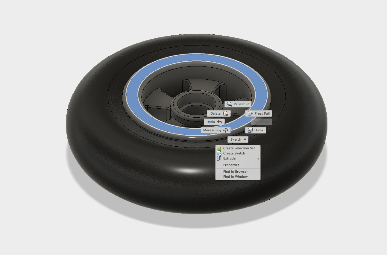 Starting a sketch on the top of the wheel hub.
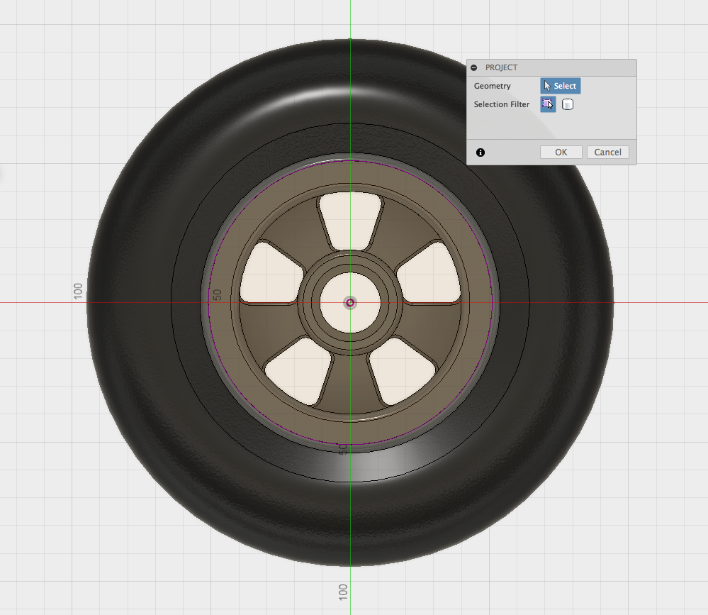 Geometry projected into the sketch.
The location of the guide holes that will be used to accurately mount the drill bushes for drilling are referenced from the wheel hub. The project tool is used to include the geometry in the sketch, enabling an accurate location of the hole relative to the wheel. A line is drawn vertically using the projected curves and a circle is added on the midpoint of the line. This circle will become the hole for the drill guide.
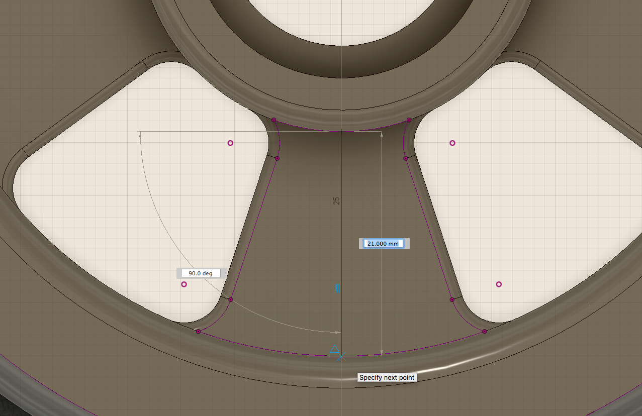 Construction line which will be used to position the circle.
The circle can be drawn once and patterned using the Circular Pattern tool in the Sketch menu which eliminates the need for additional circles to be created manually.
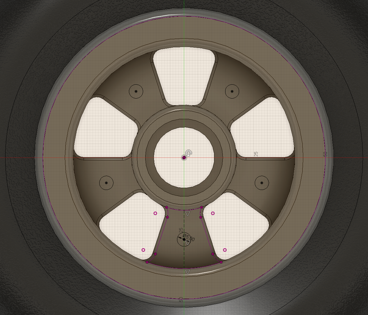 Finished sketch showing the holes patterned around the wheel.
This sketch can now be used to create the first body of the Fixture. This is achieved using an Extrude operation. Because the wheel was placed in the centre of the origin the Extrude distance can be set to the origin plane, which will be the midpoint of the wheel.
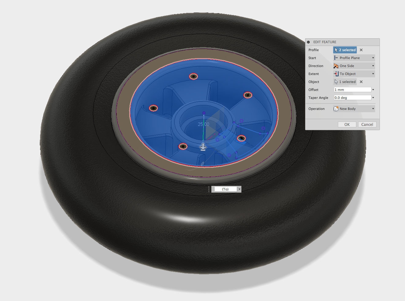 Body of the new part being extruded.
There also needs to be a gap in the middle of the parts which will allow some clearance for the 2 parts to pull together, clamping the wheel. This can be done in the Extrude operation by setting an Offset. In this case 1mm was used, which will result in a gap of 2mm when the second part is mirrored.
The top flange can now be added, this time using an Extrude operation in the upwards direction.
 Top flange extrusion.
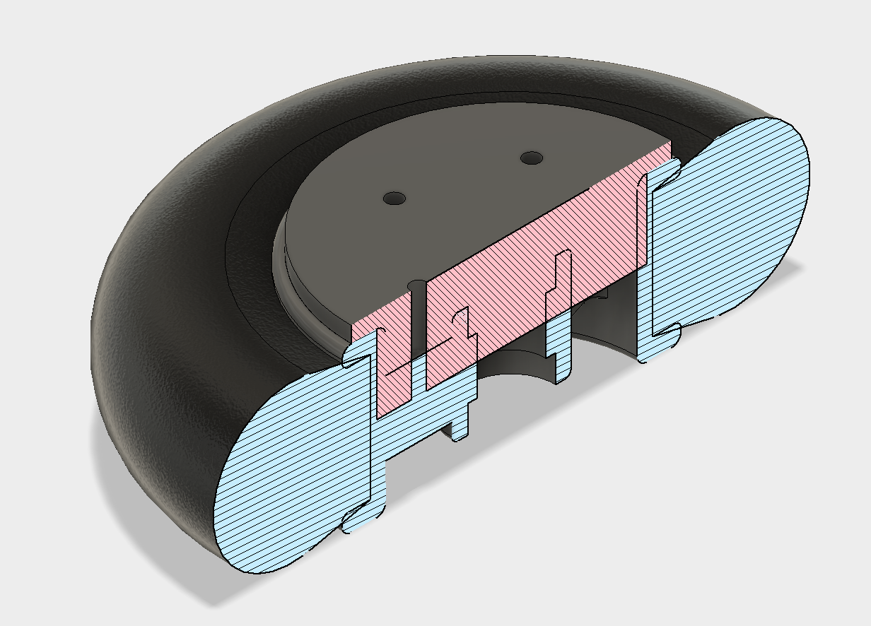 Section view showing the wheel and new fixture body before the combine operation.
The next stage is to subtract the wheel hub from the Fixture that has just been created, which is easily achieved using the Combine tool. The section view shows the two parts intersecting, which will not fit together. The wheel is used as a Tool to Cut the fixture body (Target Body), allowing clearance for the part to slot between the spokes of the wheel.
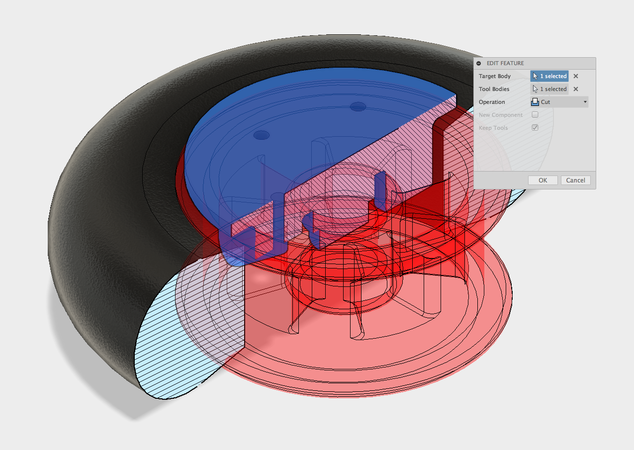 Combine operation using the wheel as a tool to cut away the fixture body wherever it intersects.
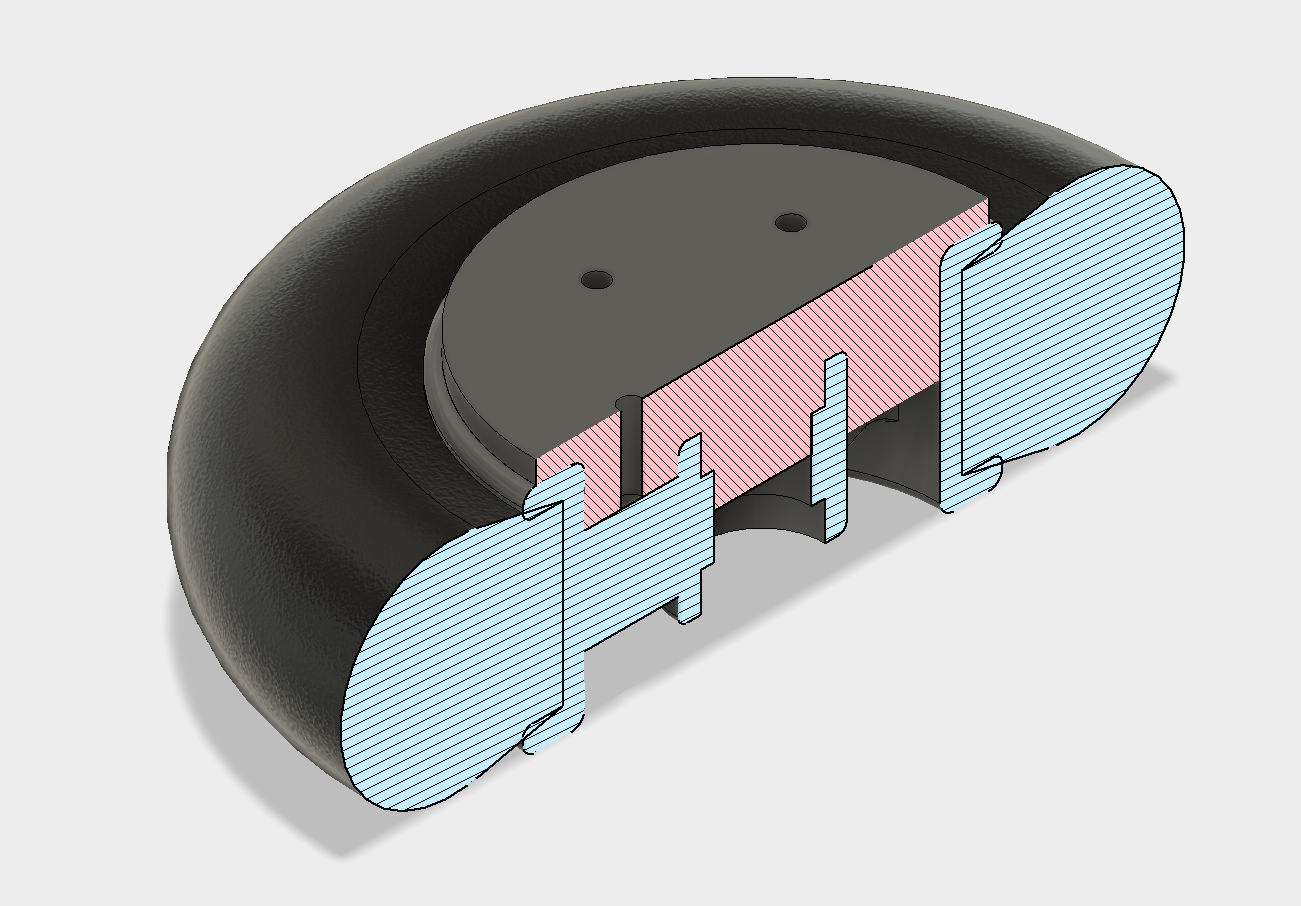 Wheel and fixture body after the combine operation.
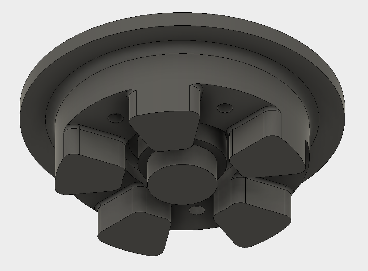 Part shown after the combine operation is completed with the cutouts for the spokes.
The final operation in this step is to add a Chamfer to the bottom edges of the part. This will assist with the assembly of the jig.
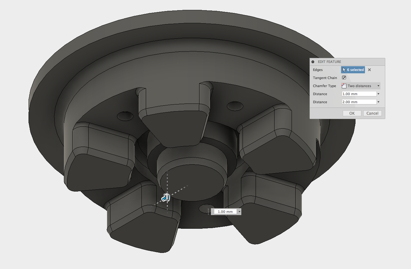 Chamfer being added to the part.
Part 3 - Drill Bushings
To ensure that the Jig feature of this part can withstand repeated drilling, drill bushes are used. These are metal inserts that guide the drill bit through the hole, and also align the drill to ensure it is perpendicular to the part. This means a slightly larger hole is required to install these in the part. This can be easily completed with an Extruded Cut feature, and also using the existing hole as a reference location, using the project command.
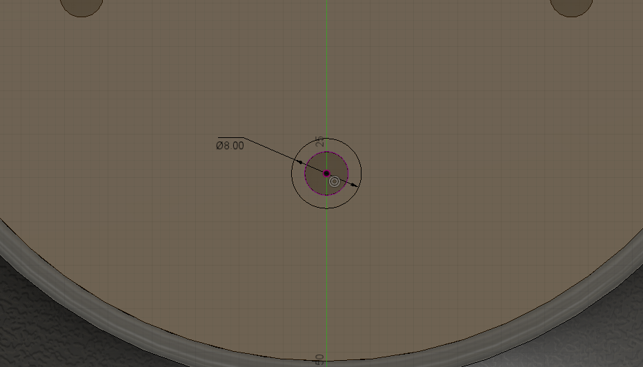 Using the existing hole to locate an 8mm circle.
The drill bushes used in this part have an 8mm outside diameter so an 8mm circle is sketched onto the top of the Jig & Fixture part and Extruded down by the length of the drill bushing (in this case it is -16mm).
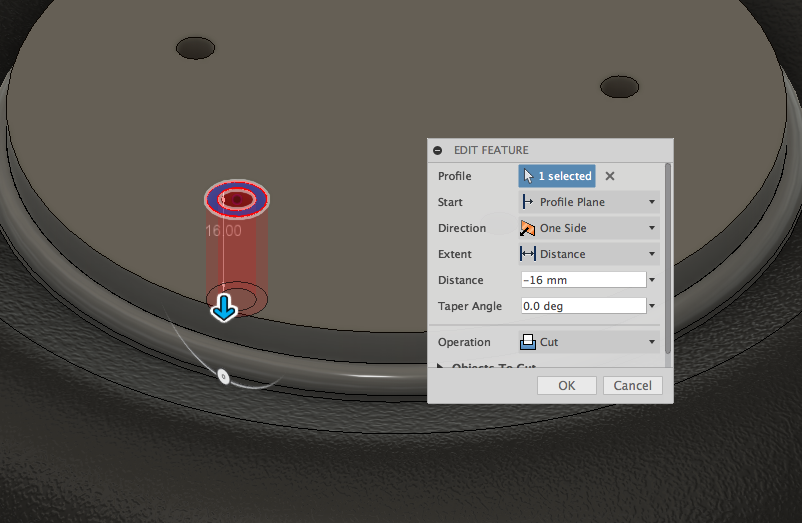 Extruding the hole for the drill bushing.
Now that this operation has only been completed on one of the holes, the circular pattern tool can be used to pattern the feature to the required locations. The Pattern Type is set to Features.
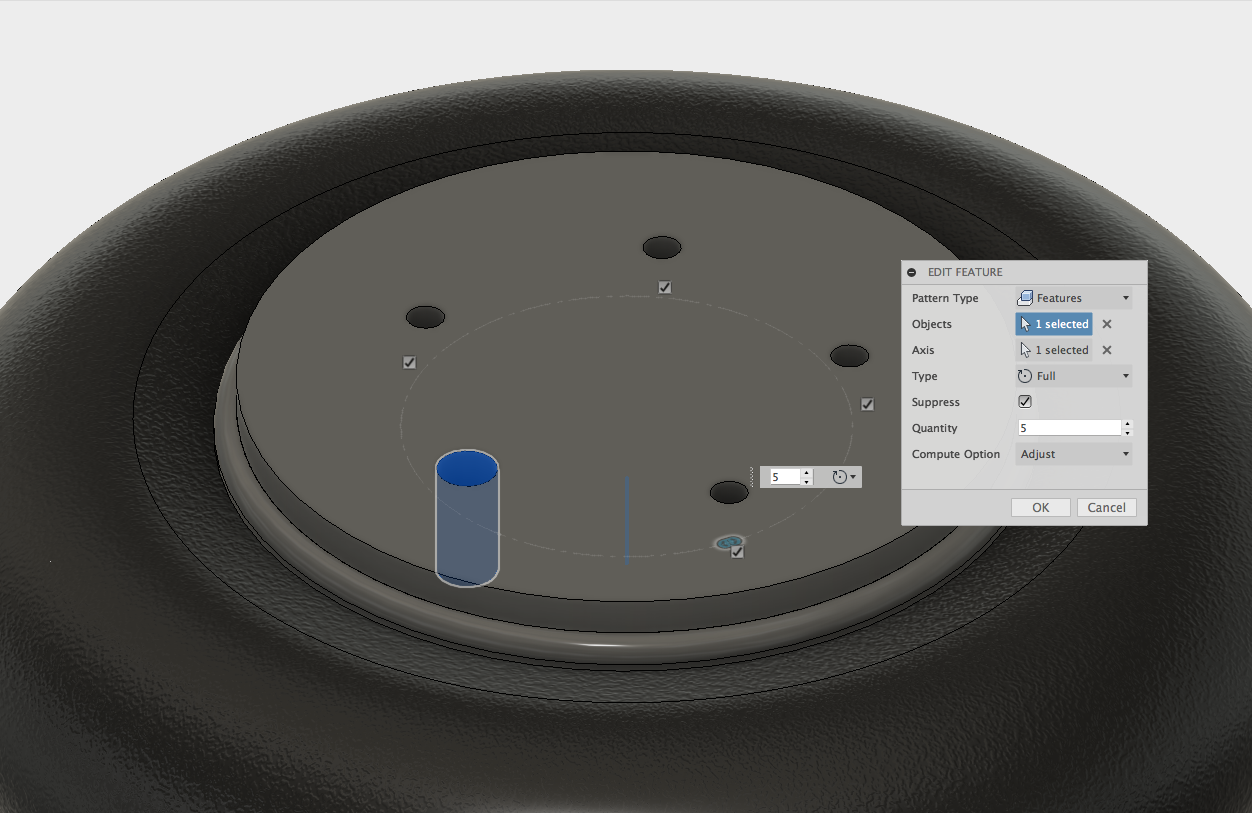 Circular patterning the drill bushing holes.
Part 3a - Inserting Drill Bushings
It is possible to insert the actual drill bushing from the manufacturer by using the ‘Insert McMaster-Carr Component’ via the Insert menu. This allows the exact component to be selected and imported into the assembly. McMaster-Carr have a large collection of components with 3D files that can be easily imported into Fusion.
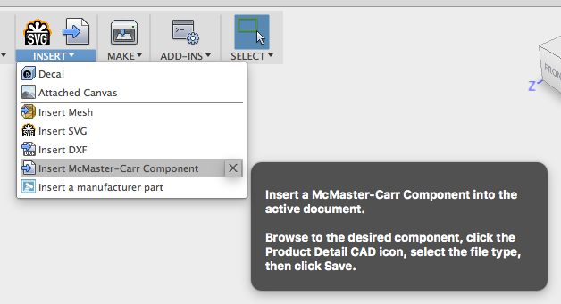 Insert McMaster-Carr Component menu.
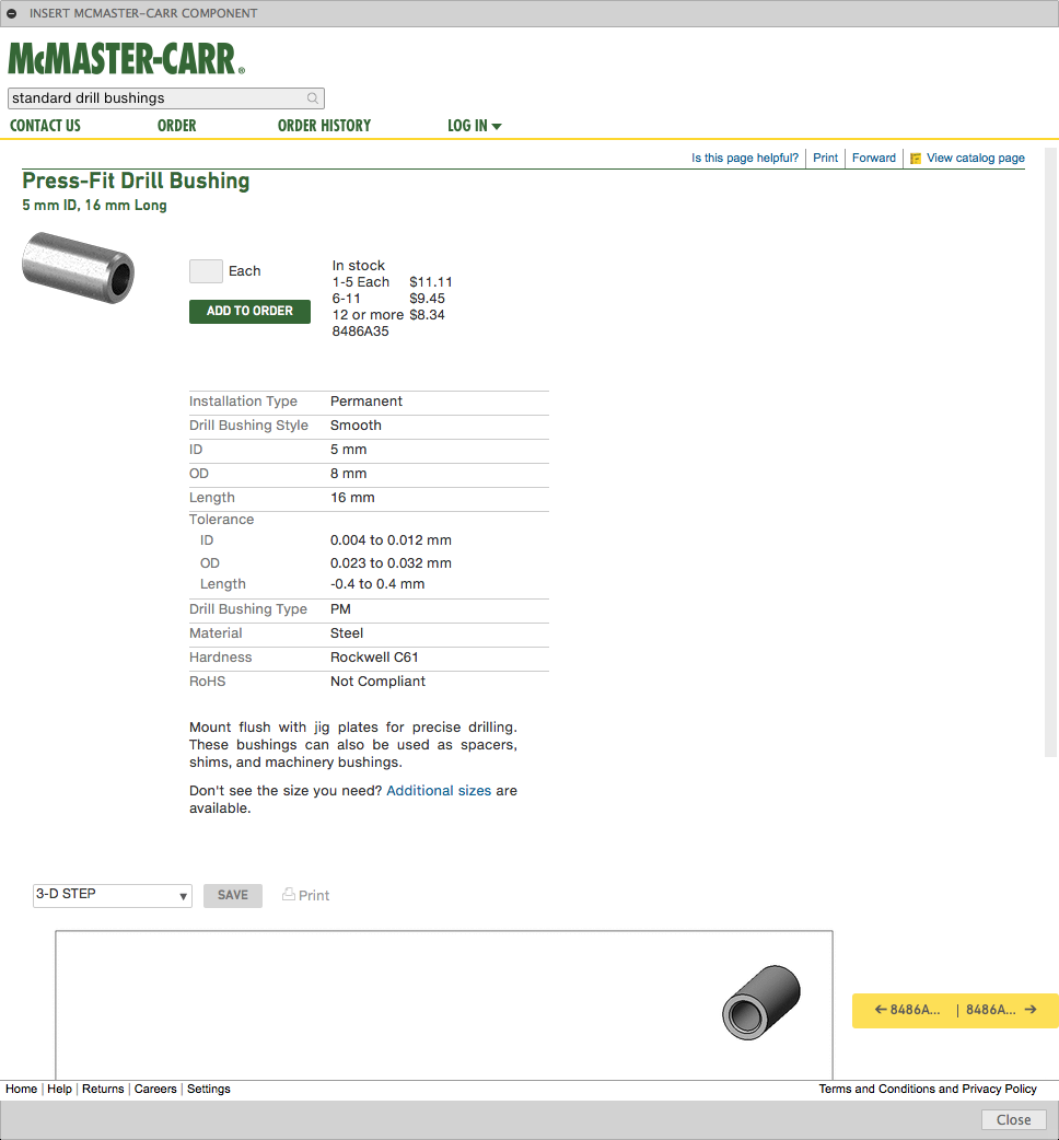 McMaster-Carr component page, with the desired part identified.
Once the part is located the 3D file can be imported into Fusion by selecting the file type. For these types of models a STEP file is recommended. The part can now be imported into the existing Fusion file.
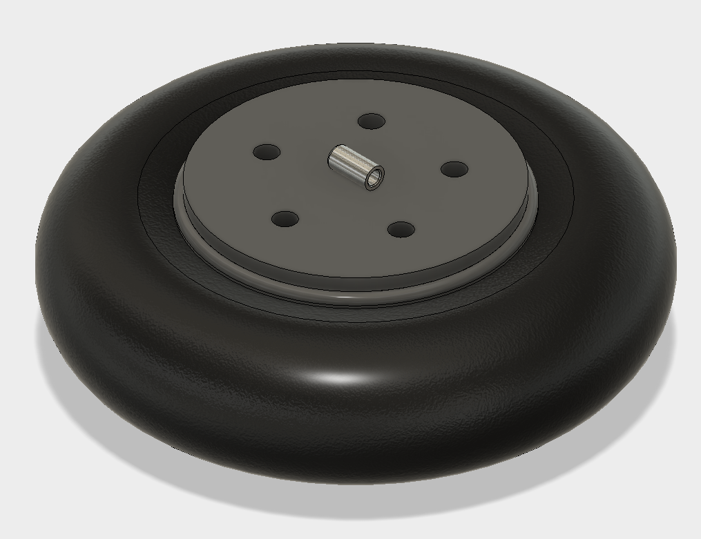 Part imported into the Fusion file.
The Joint command can now be used to align the drill bushing into position. The top of the drill bushing is selected first and then the hole allowing the assembly operation to take place.
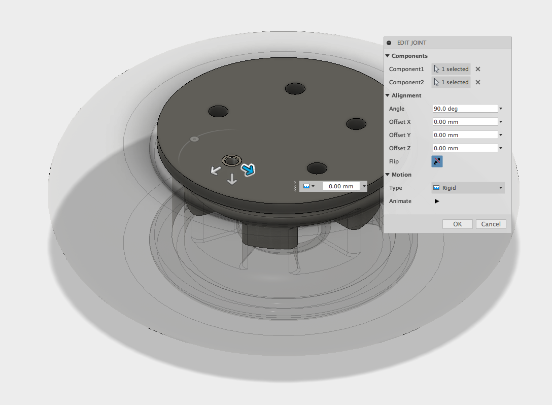 Joint command positioning the drill bushing into the hole.
The Circular Pattern Command is used again to copy the component to each hole location, eliminating the need to repeat the Insert and Joint commands for each bushing.
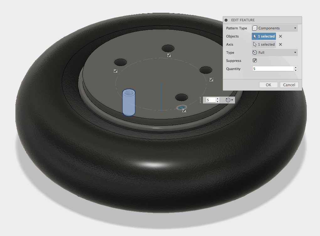 Circular pattern command used to copy the drill bushings to each hole.
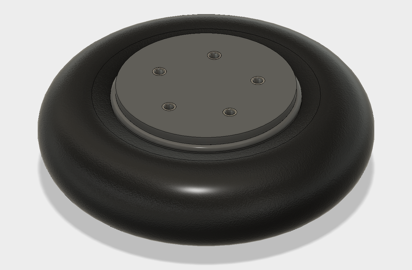 Completed circular pattern with 5 drill bushings.
Part 4 - Mirroring Bottom Side
Next, the bottom section of the jig and fixture is created. Because the wheel is symmetrical, it is possible to simply mirror the existing body, creating a second body that can be used to secure the wheel during the drilling operations.
When the main body was Extruded in step 2, an offset of 1mm was added which resulted in the part having a gap of 1mm from the origin. As discussed earlier this was intentionally done to leave some space when the 2 pieces clamp the wheel together. Without this gap, the Jig & Fixture halves would both meet one another, and not clamp the wheel securely.
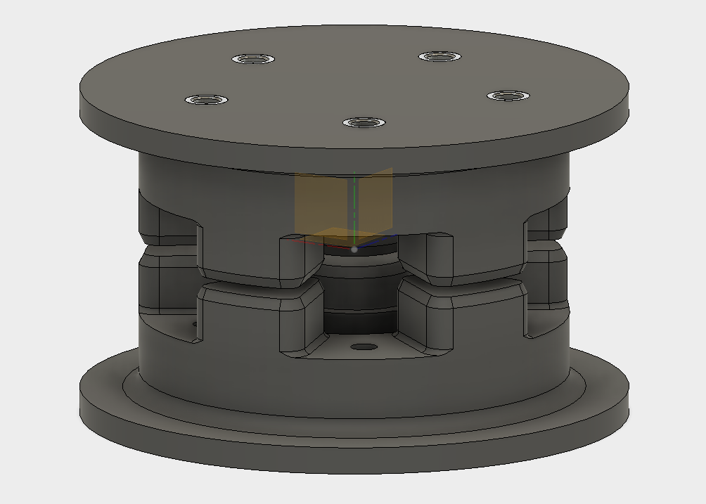
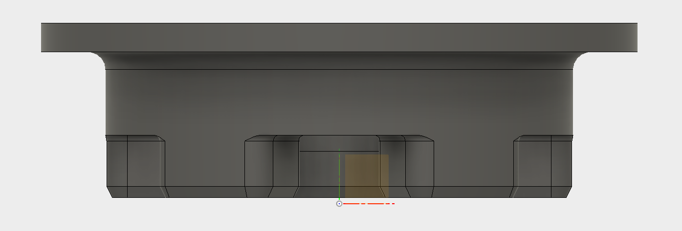 The origin 1mm below the bottom of the part.
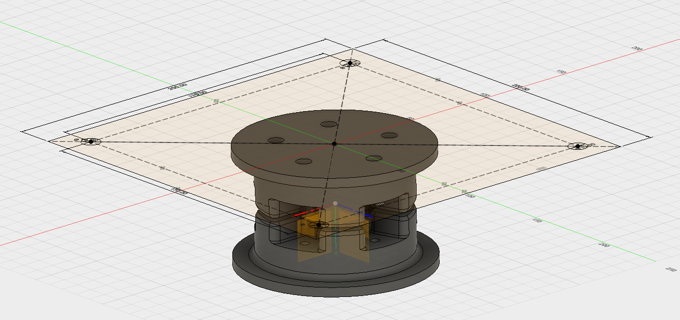
The part can now be mirrored using the origin plane, which will also mirror the 1mm gap, resulting in a 2mm gap between the two halves.
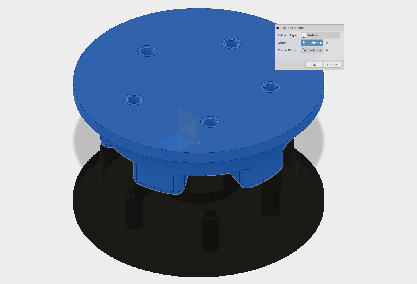 Mirrored body viewed from the top.
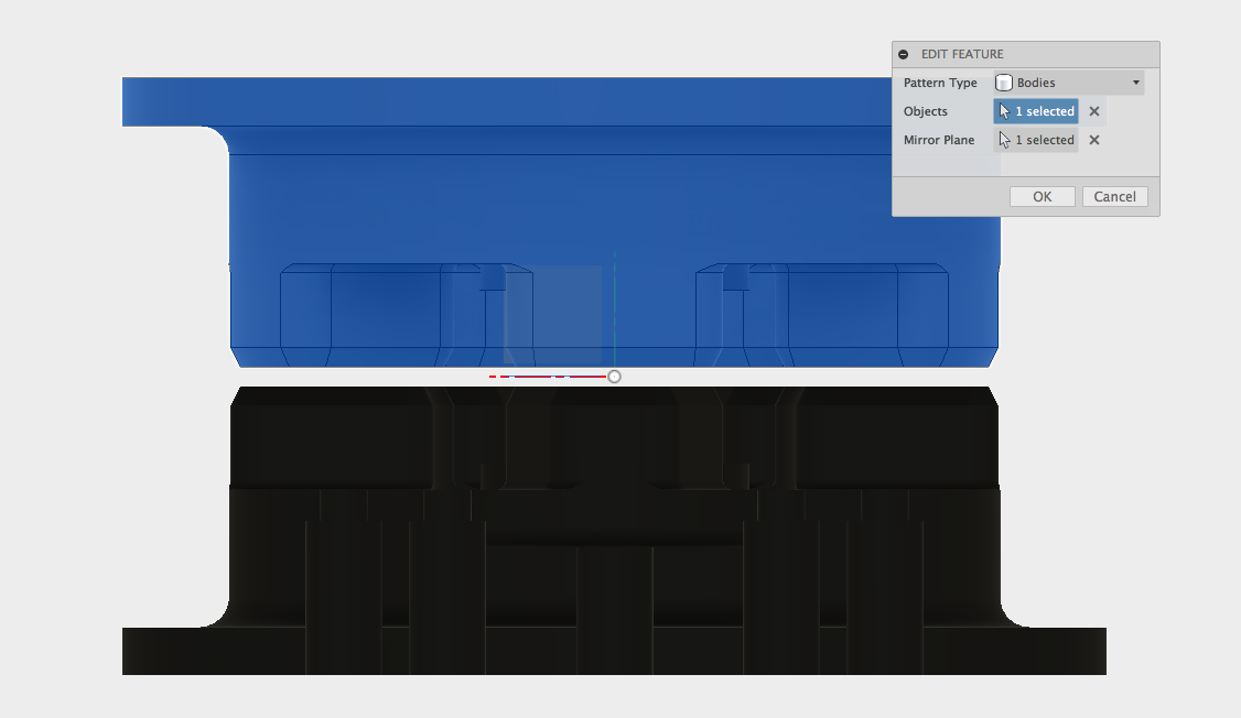 Side view of the mirror feature.
 Completed mirror of the part.
Part 5 - Base
Because this design will become a production tool for modifying the wheels it will need to be mounted to a workbench for continuous use. A base can now be added with holes which can be used to screw the Jig & Fixture in place.
 Sketch for the base.
First a sketch is created on the bottom of the lower part. A simple center rectangle is drawn for the main base and circles are added at the corners. These will act as clearance holes for the screws which will mount the part to the workbench.
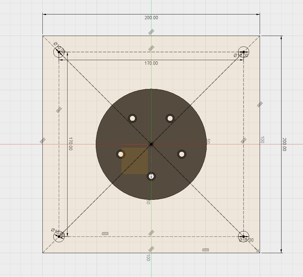 Sketch for the base.
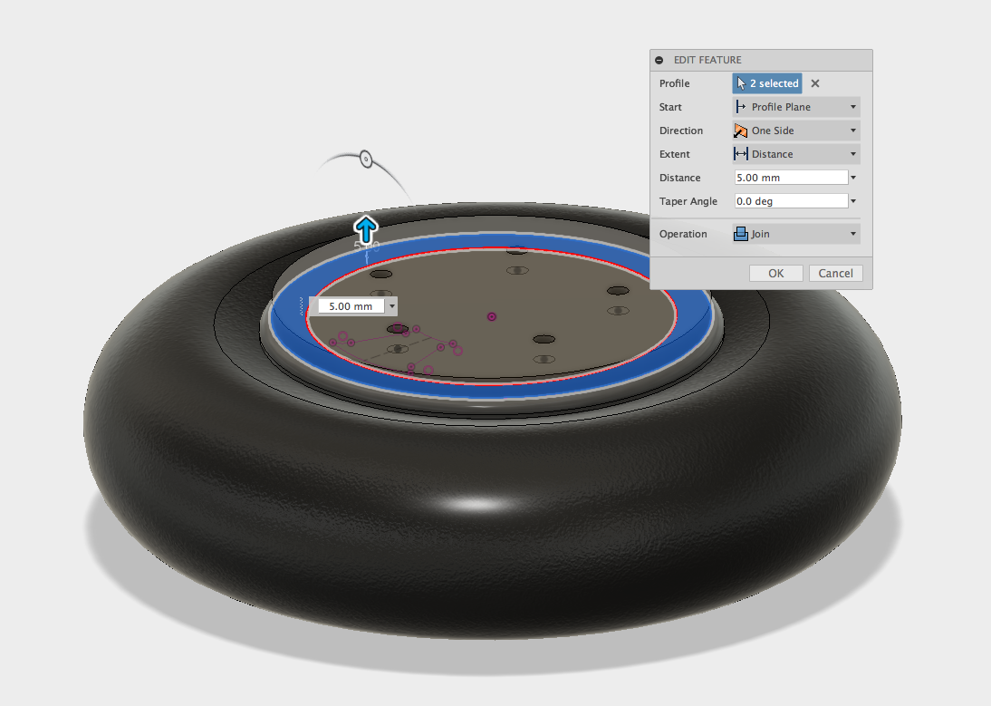
The sketch is then extruded up to a depth of 5mm, joining it with the base section of the jig.
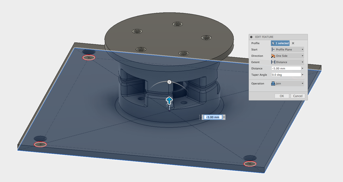 Extrusion for the base.
The final stage of the base is to add some Chamfers and Fillets. These are for aesthetic reasons, as well as eliminating any sharp corners which will speed up printing time as the printer does not have to change direction as vigorously.
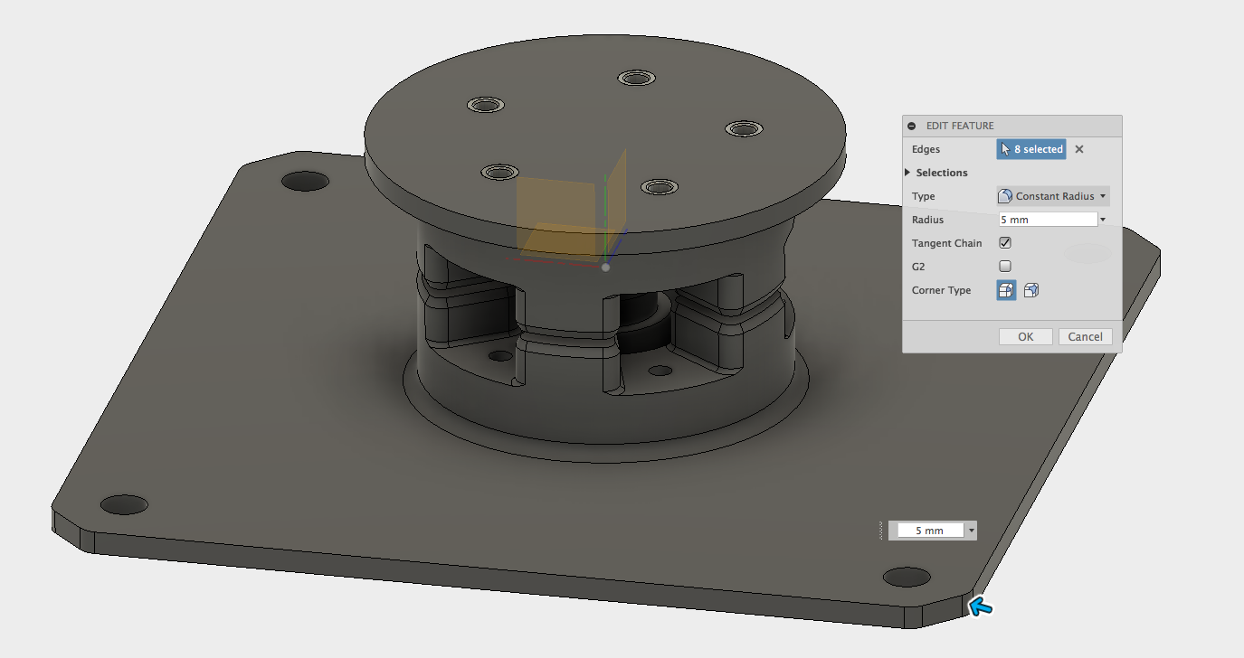 Part with chamfers and fillets added.
Part 6 - Screw Clamp
The mechanism for clamping the two halves together will consist of a simple bolt and nut. The bolt will remain in place and the top part will be removable; fastened by a nut screwed down from the top. A hole needs to be created through the entire part and a hexagon cut out from the bottom which will hold the bolt head and prevent it from twisting. Both features can be created from the same sketch.
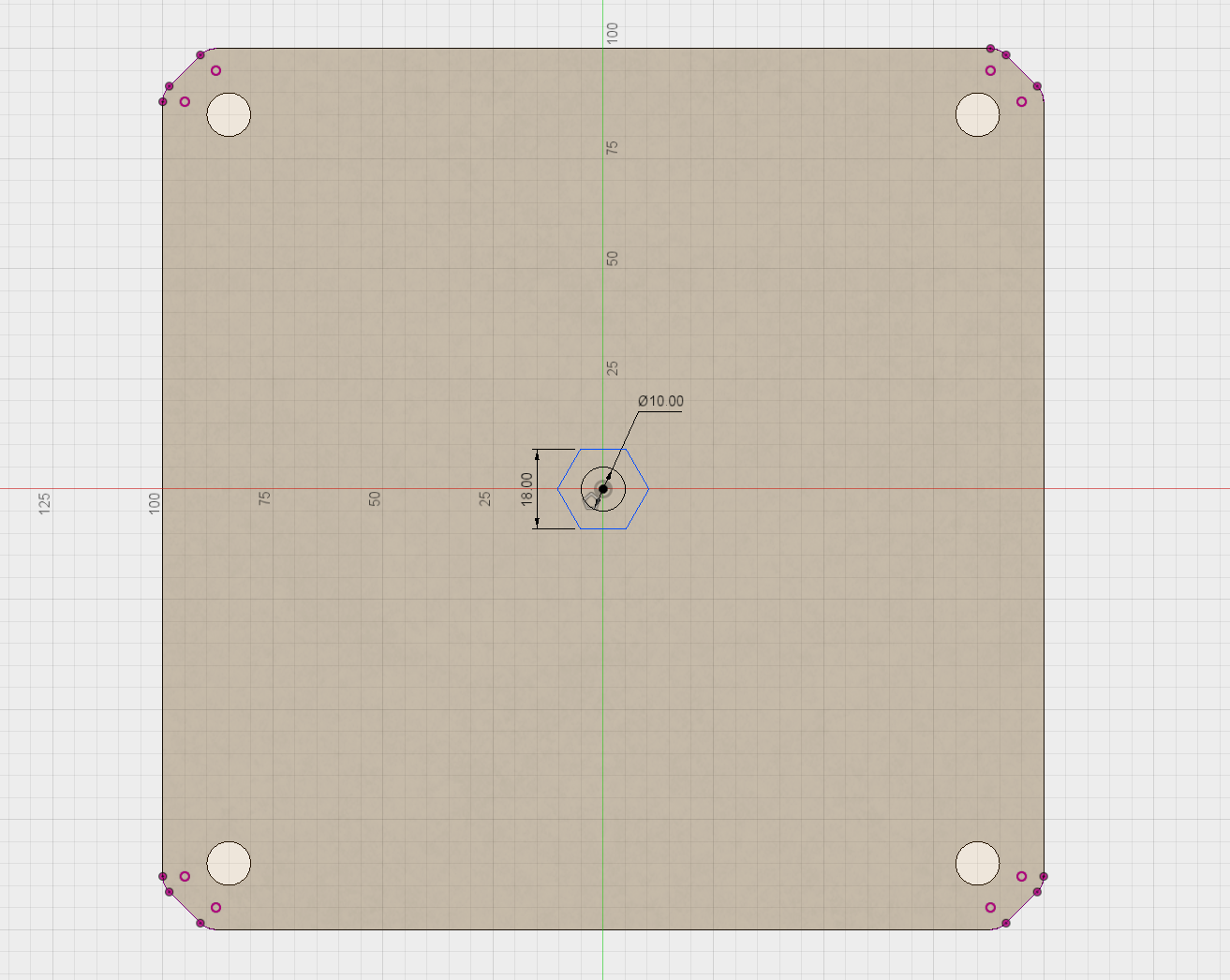 Sketch showing hex and circle.
An M10 bolt will be used for this part, with an 18mm width across the flats, so the hexagon was sketched to match. Usually a little extra space would be added to allow for a clearance fit, however the bolt needs to be secured so can be pressed in for a tight fit. The 10mm hole for the bolt can also be added to this sketch. You can read more about using threaded fastners here.
The sketch can then be used to extrude cut through the parts, creating the clearance for the bolt.
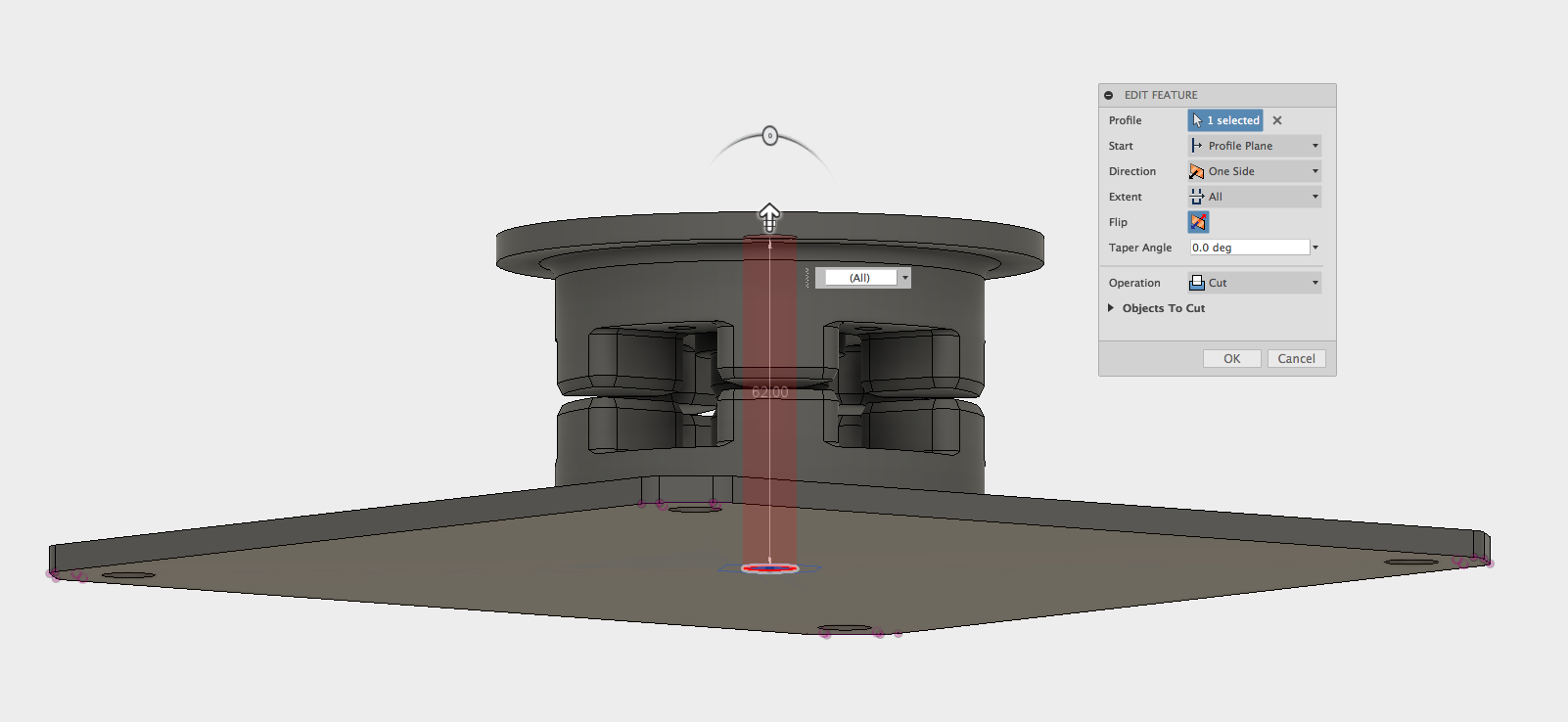 Bolt hole extrusion (8mm).
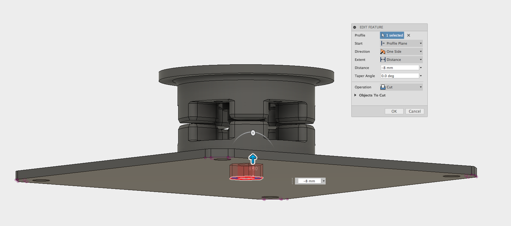 Hex cavity extrusion.
Part 6 - Finishing
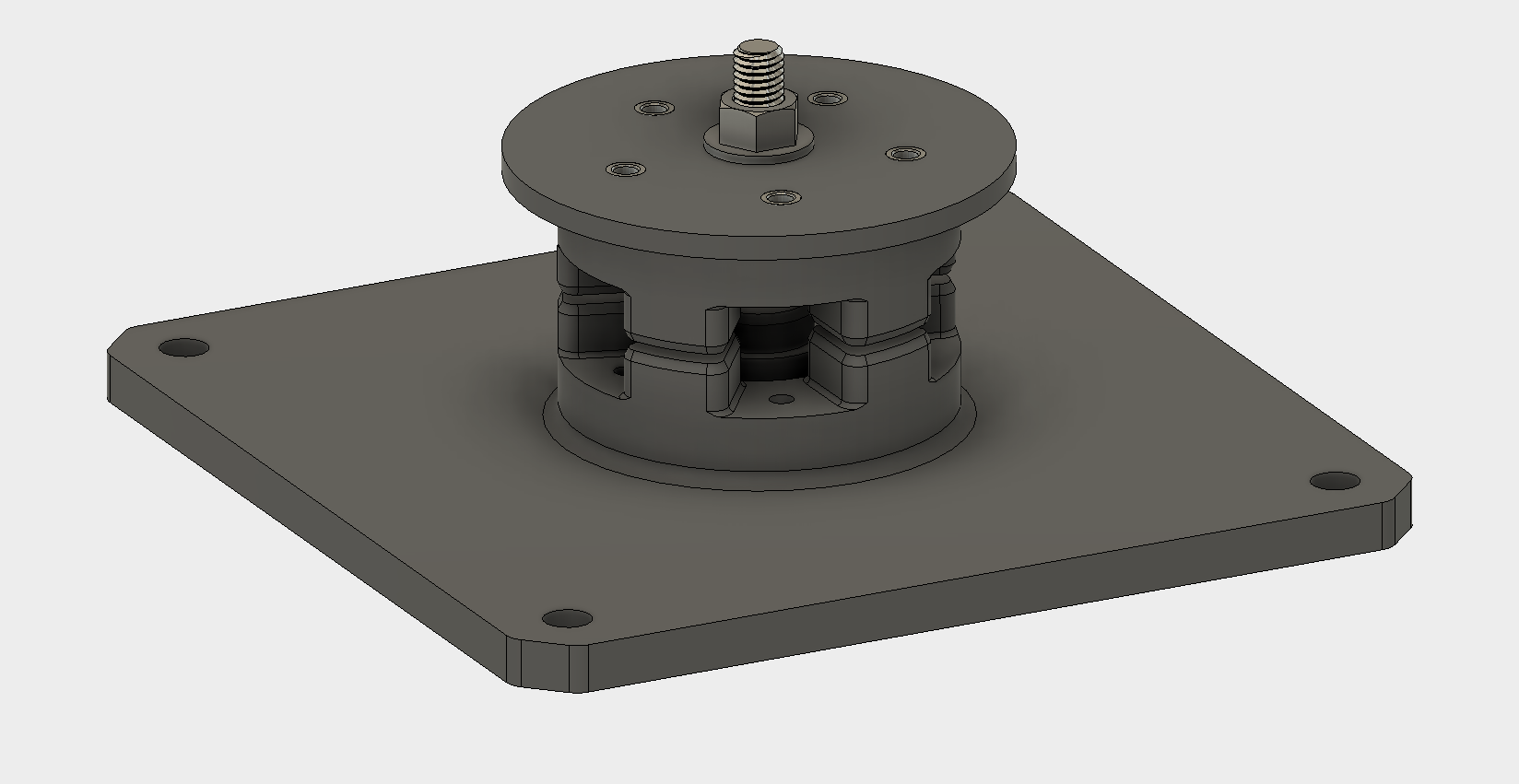
The main design work for the Jig & Fixture is now complete, the final step is to add the bolt and nut to ensure everything looks correct before printing. This is also added from the McMaster-Carr import menu.
The parts can now be printed and used for drilling the accurate holes needed for the modification of the wheels. If you would like to take a more in depth look at this model you can download the Fusion 360 file and also the STL files.
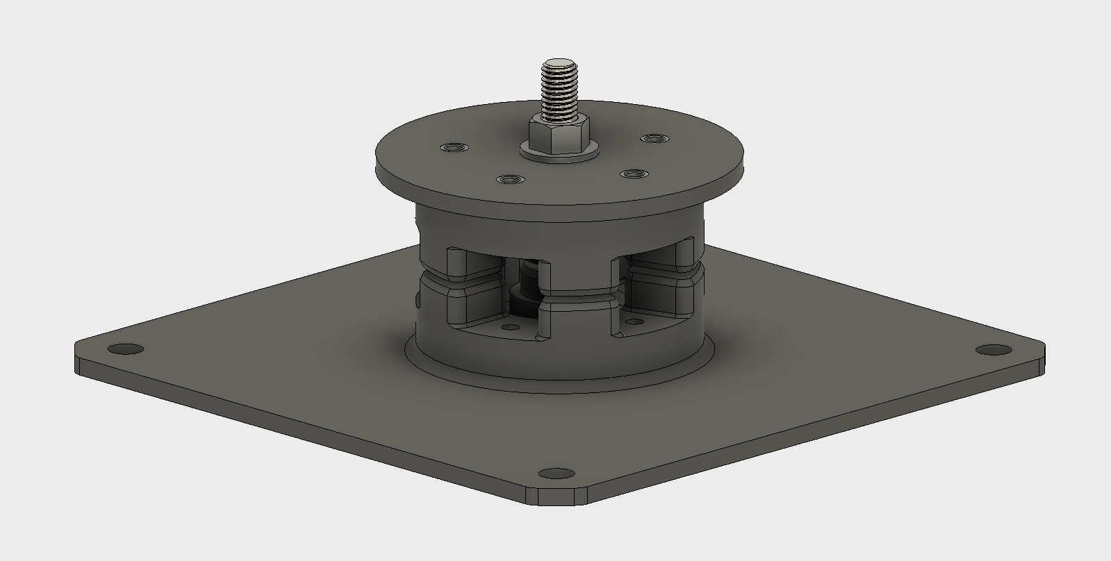 Completed Jig & Fixture.
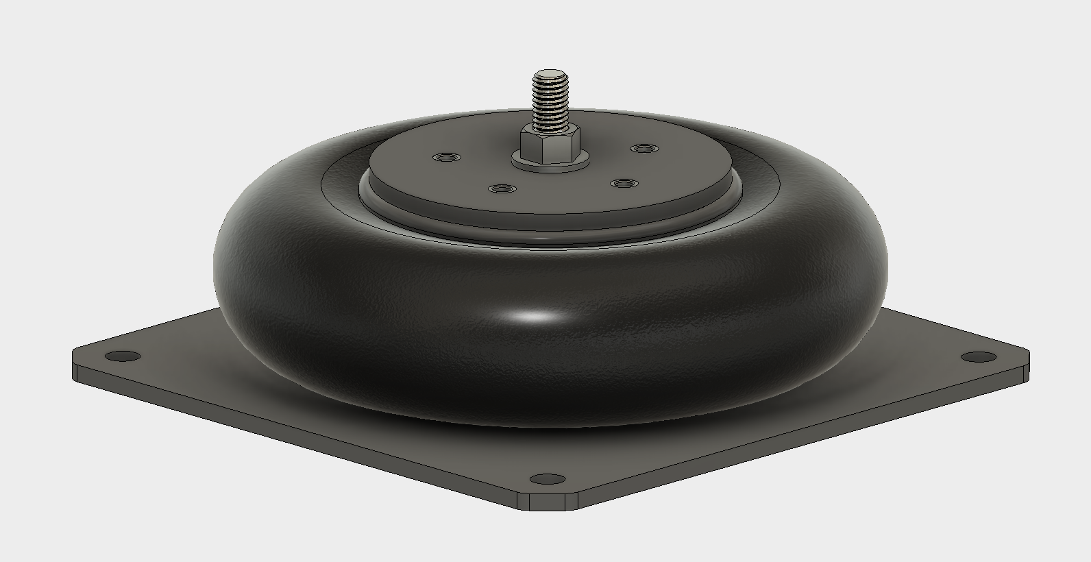 Completed Jig & Fixture with wheel ready for drilling.
Learn more from our in-depth 3D printing guide here.