


The Complete Engineering Guide
CNC machining

Ready to get your parts machined?
Get instant CNC quote
SHARE THIS ARTICLE
SHARE THIS ARTICLE
Learn all you need to know about CNC machining in 25 minutes or less. Whether you are an experienced design engineer or just getting started with CNC, this guide is for you.
Part 1
The basics
What is CNC machining? What are the different types of CNC machines? How do they work?
In this section, we answer all these questions and we compare CNC machining to other manufacturing technologies to help you find the best solution for your application.
What is CNC machining?
CNC (Computer Numerical Control) machining is a subtractive manufacturing technology: parts are created by removing material from a solid block (called the blank or the workpiece) using a variety of cutting tools.
This is a fundamentally different way of manufacturing compared to additive (3D printing) or formative (Injection Molding) technologies. The material removal mechanisms have significant implications on the benefits, limitations and design restrictions of CNC. More on this below.
CNC machining is a digital manufacturing technology: it produces high-accuracy parts with excellent physical properties directly from a CAD file. Due to the high level of automation, CNC is price-competitive for both one-off custom parts and medium-volume productions.
Almost every material can be CNC machined. The most common examples include metals (aluminum and steel alloys, brass etc) and plastics (ABS, Delrin, Nylon etc). Foam, composites and wood can also be machined.
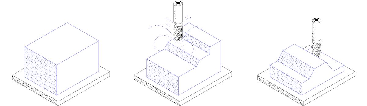
The basic CNC process can be broken down into 3 steps. The engineer first designs the CAD model of the part. The machinist then turns the CAD file into a CNC program (G-code) and sets up the machine. Finally, the CNC system executes all machining operations with little supervision, removing material and creating the part.
A brief history of CNC machining
- The earliest machined object ever discovered was a bowl found in Italy and made in 700 B.C. using a lathe.
- Attempts to automate machining started in the 18th century. These machines were purely mechanical and powered by steam.
- The first programmable machine was developed in the late 40’s in MIT. It used punched cards to encode each movement.
- The proliferation of computers in the 50’s and 60’s added the “C” in CNC and radically changed the manufacturing industry.
- Today, CNC machines are advanced robotic systems with multi-axis and multi-tooling capabilities.

Types of CNC machines
In this guide, we will focus on CNC machines that remove material using cutting tools. These are the most common and have the widest range of applications. Other CNC machines include laser cutters, plasma cutters and EDM machines.
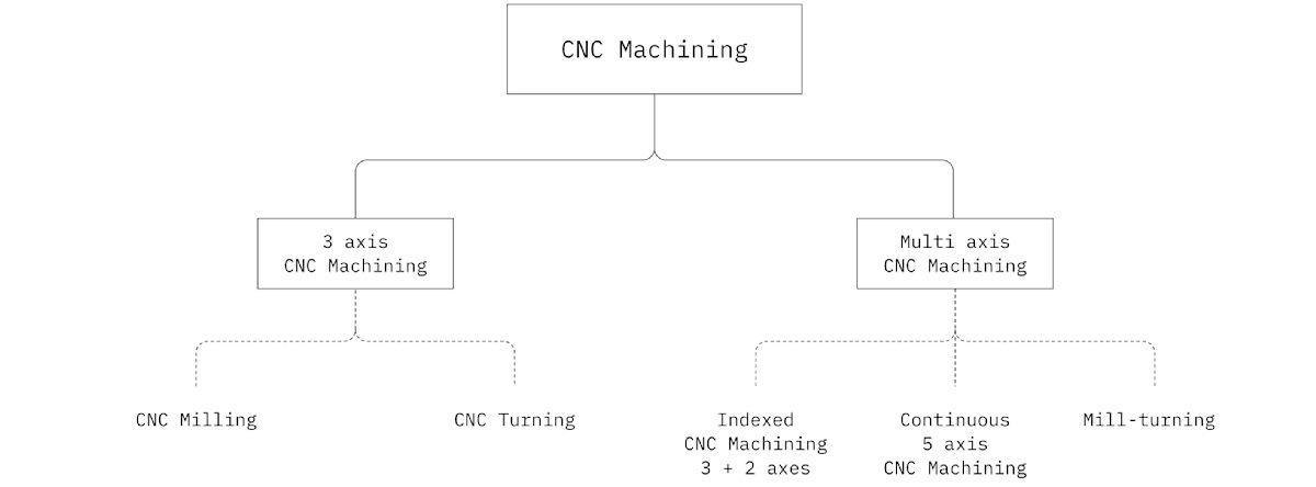
3-axis CNC machines
CNC milling and CNC turning machines are examples of 3-axis CNC systems. These “basic” machines allow the movement of the cutting tool in three linear axes relative to the workpiece (left-right, back-forth and up-down).
CNC milling
- The workpiece is held stationary directly on the machine bed or in a vice.
- Material is removed from the workpiece using cutting tools or drills that rotate at high speed.
- The tools are attached to a spindle, which can move along three linear axis.

3-axis CNC milling machines are very common, as they can be used to produce most common geometries. They are relatively easy to program and operate, so start-up machining costs are relatively low.
Tool access can be a design restriction in CNC milling. As there are only three axes to work with, certain areas might be impossible to reach. This is not a big issue if the workpiece needs to be rotated just once, but if multiple rotations are needed the labor and machining costs increase fast.
Learn more about CNC milling →
Explore the full range of CNC milling capabilities available on Protolabs Network →

CNC turning (lathes)
- The workpiece is held on the spindle while rotating at high speed.
- A cutting tool or center drill traces the outer or inner perimeter of the part, forming the geometry.
- The tool does not rotate and moves along polar directions (radially and lengthwise).

CNC lathes are extensively used, because they can produce parts at a much higher rate and at a lower cost per unit than CNC mills. This is especially relevant for larger volumes.
The main design restriction of CNC lathes is that they can only produce parts with a cylindrical profile (think screws or washers). To overcome this limitation, features of the part are often CNC milled in a separate machining step. Alternatively, 5-axis mill-turning CNC centers can be used to produce the same geometry in one step.
Learn more about CNC turning →
Explore the full range of CNC turning capabilities available on Protolabs Network →

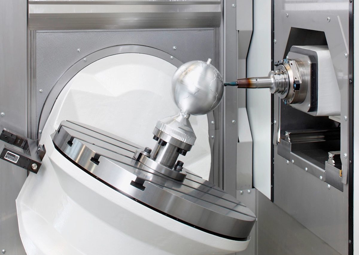
5-axis CNC machining
Multi-axis CNC machining centers come in three variations: 5-axis indexed CNC milling, continuous 5-axis CNC milling and mill-turning centers with live tooling.
These systems are essentially milling machines or lathes enhanced with additional degrees of freedom. For example, 5-axis CNC milling centers allow the rotation of the machine bed or the toolhead (or both) in addition to the three linear axes of movement.
The advanced capabilities of these machines come at an increased cost. They require both specialized machinery and also operators with expert knowledge. For highly complex or topology optimized metal parts, 3D printing is usually a more suitable option though.
Indexed 5-axis CNC milling
- During machining the cutting tool can only move along three linear axis.
- Between operations the bed and the toolhead can rotate, giving access to the workpiece from a different angle.
Indexed 5-axis CNC milling systems are also known as 3+2 CNC milling machines, since they are using the two additional degrees of freedom only between machining operations to rotate the workpiece.
The key benefit of these systems is that they eliminate the need of manually repositioning the workpiece. This way parts with more complex geometries can be manufactured faster and at higher accuracy than in a 3-axis CNC mill. They lack though the true freeform capabilities of continuous 5-axis CNC machines.
Explore the full range of 5-axis CNC milling capabilities available on Protolabs Network →
Continuous 5-axis CNC milling
- The cutting tool can move along three linear and two rotational axes relative to the workpiece.
- All five axes can move at the same during all machining operations.

Continuous 5-axis CNC milling systems have a similar machine architecture to indexed 5-axis CNC milling machines. They allow, however, for the movement of all five axes at the same time during all machining operations.
This way, it is possible to produce parts with complex, ‘organic’ geometries that cannot be manufactured at the achieved level of accuracy with any other technology. These advanced capabilities come of course at a high cost, as both expensive machinery and highly-trained machinists are needed.
Explore the full range of 5-axis CNC milling capabilities available on Protolabs Network →
Mill-turning CNC centers
-
The workpiece is attached to a spindle that can either rotate at high speed (like a lathe) or position it at a precise angle (like a 5-axis CNC mill).
-
Lathe and milling cutting tools are used to remove material from the workpiece, forming the part.

Mill-turning CNC centers are essentially CNC lathe machines equipped with CNC milling tools. A variation of the mill-turning centers are swiss-style lathes, which have typically higher precession.
Mill-turning systems take advantage of both the high productivity of CNC turning and the geometric flexibility of CNC milling. They are ideal for manufacturing parts with ’loose’ rotational symmetry (think camshafts and centrifugal impellers) at a much lower cost than other 5-axis CNC machining systems.
Explore the full range of CNC mill-turning capabilities available on Protolabs Network →
To summarize
- 3-axis CNC milling machines manufacture parts with relatively simple geometries with excellent accuracy and at a low cost.
- CNC lathes have the lowest cost per unit, but are only suitable for part geometries with rotational symmetry.
- Indexed 5-axis CNC milling machines manufacture parts with features that do not align with one of the main axes quickly and with very high accuracy.
- Continuous 5-axis CNC milling machines manufacture parts with highly complex, ‘organic’ geometries and smooth contours, but at a high cost.
- Mill-turning CNC centers combine the benefits of CNC turning and CNC milling into a single system to manufacture complex parts at a lower cost than other 5-axis CNC systems.
Use the table below for a rough estimate of the cost per hour of the different CNC machines. The cost is presented relative to that of a 3-axis CNC milling machine, which is typically $75 per hour.
| CNC machine type | Machining cost |
|---|---|
| CNC milling (3-axis) | $75 ( Baseline for comparison ) |
| CNC turning (lathe) | $65 ( - 15% ) |
| Indexed 5-axis CNC milling | $120 ( + 60% ) |
| Continuous 5-axis CNC milling | $150 ( + 100% ) |
| Mill-turning CNC centers | $95 ( + 25% ) |
Benefits & Limitations of CNC machining
Here’s a list of the key strengths and limitations of CNC machining. Use them to help you decide whether it is the right technology for your application.
Benefits of CNC machining
CNC machining can create parts with greater dimensional accuracy than most other common manufacturing technologies. During the final finishing machining steps, material can be removed from the workpiece very accurately, achieving very tight tolerances.
The standard tolerance of any dimension in CNC machining is ± 0.125 mm. Features with tighter tolerance down to ± 0.050 mm can be manufactured and even tolerances of ± 0.025 mm are feasible. That is about a quarter the width of a human hair!
CNC machined parts have excellent physical properties, identical to the bulk material. This makes them ideal for applications where high-performance is essential.
Additionally, virtually every common material with enough hardness can be CNC machined. This gives engineers the flexibility to select a material with optimal properties for their application.
The advances of modern CNC systems, CAM software, and digital supply chains have greatly accelerated the production times. Now CNC machined parts are typically ready for delivery within 5 days. This is comparable to the turnaround of industrial 3D printing processes, such as SLS.
In contrast to formative technologies (Injection Molding), CNC machining does not need any special tooling. So, the on-demand production of custom one-off parts and prototypes is economically viable. This is especially relevant for one-off custom metal parts and prototypes, where CNC is the most cost-competitive solution.
CNC machining is also a very price-competitive option for manufacturing small-to-medium volumes (from 10’s to 100’s). In fact, when ordering 10 identical parts, the unit price is cut by about 70% compared to a one-off part . This is because ’economies of scale’ start to kick in: the relatively high start-up costs of CNC are spread over multiple parts.
In contrast, additive technologies (3D printing) do not scale as well for higher volumes - the unit price is relatively stable. Formative technologies (Injection Molding or Investment Casting) only make economic sense for production volumes in the 1000’s - they have very high start-up costs.
Limitations of CNC machining
In CNC machining, start-up costs are mainly connected to process planning. This step requires manual input from an expert, so start-up costs are usually relatively high when compared, for example, to 3D printing, where process planning is highly automated. They are still much lower than formative manufacturing processes though (Injection Molding or Investment Casting), which require the preparation of custom tooling.
It is important to keep in mind that start-up costs are fixed. There is an opportunity to significantly reduce the unit price per part by taking advantage of ’economies of scale’, as we saw above.
Being a subtractive technology, machining complex geometries come at an increased cost. It is also restricted by the mechanics of the cutting process. Parts with complex geometry either require the use of a multi-axis CNC machining system or manual labor from the machinist (repositioning, realigning etc).
To help you keep the price of CNC machined parts to a minimum, we’ve compiled a list of design tips.
Since a part is produced by removing material from a solid block, a cutting tool with a suitable geometry must exist. It should also be able to access all necessary surfaces. For this reason parts with internal geometries or very steep undercuts (for example) cannot be machined.
Holding the workpiece securely in place is essential for CNC machining and introduces certain design limitation. Improper workholding or a workpiece with low stiffness can lead to vibrations during machining. This results to parts with lower dimensional accuracy. Complex geometries might require custom jigs or fixtures.
Applications of CNC machining
One of the greatest things about CNC machining is the wide range of applications it has found over the years.
Here, we collected some recent examples to illustrate how professionals have exploited the benefits of CNC machining to get the best results in different industrial situations. Use them as inspiration for your projects.
Space
CNC machining is one of the very few manufacturing processes that is suitable for creating parts for space applications. Not only because of CNC parts have excellent accuracy and material properties, but also due to the wide range of surface treatments that can be applied to the parts after machining.
For example, KEPLER used CNC machining and space grade materials to go from a sketch on a napkin to a satellite in space in 12 months.
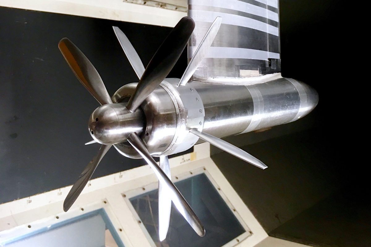
Aerospace
Aerospace was one of the first industries to use CNC machining. This is due to its ability to manufacture lightweight parts with excellent physical properties and very tight tolerances. CNC machining is used both for aircraft parts and also during the development stages.
For example, Tomas Sinnige is a PhD researcher at the Delft University of Technology. With his team of researchers, they used CNC machining to manufacture scaled-down versions of their prototype engine, aiming to increase the efficiency of modern propeller engines.
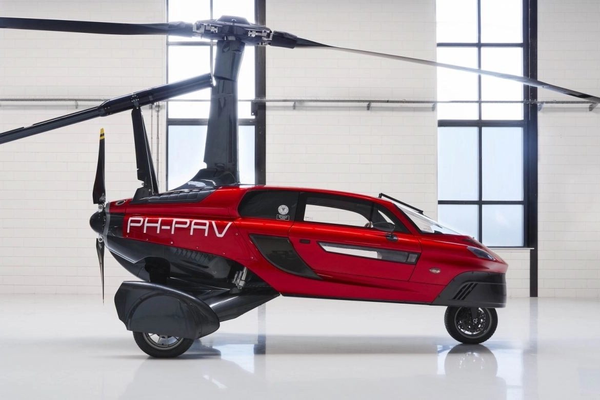
Automotive
CNC machining has applications in the automotive industry when manufacturing of high-performance custom parts is required.
For example, the Dutch company PAL-V, designs Personal Air and Land Vehicles. These are essentially the world’s first flying cars. During the development stages, they chose CNC machining to prototype and manufacture key components.
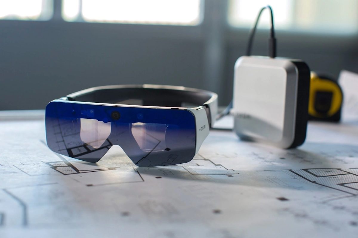
Product Design & Development
The ability of manufacture quickly custom metal parts with great dimensional accuracy, makes CNC machining an attractive option for producing functional prototypes. This is essential during later stages of design and development.
The design team of DAQRI, for instance, used CNC machining to prototype their professional Augmented Reality (AR) hardware. They selected this process, as it was the most cost-competitive solution that was capable of producing custom metal parts with the required level of detail and at the small-scale needed for their designs.
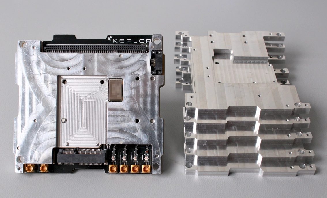
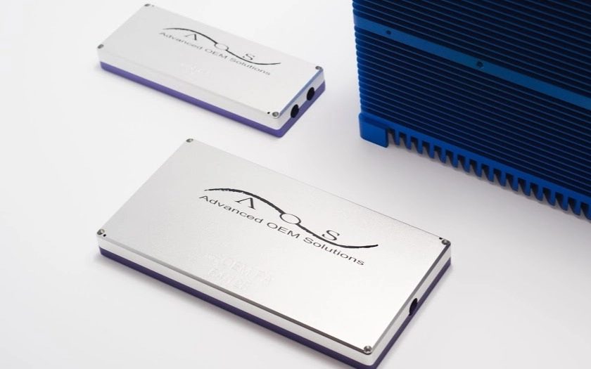
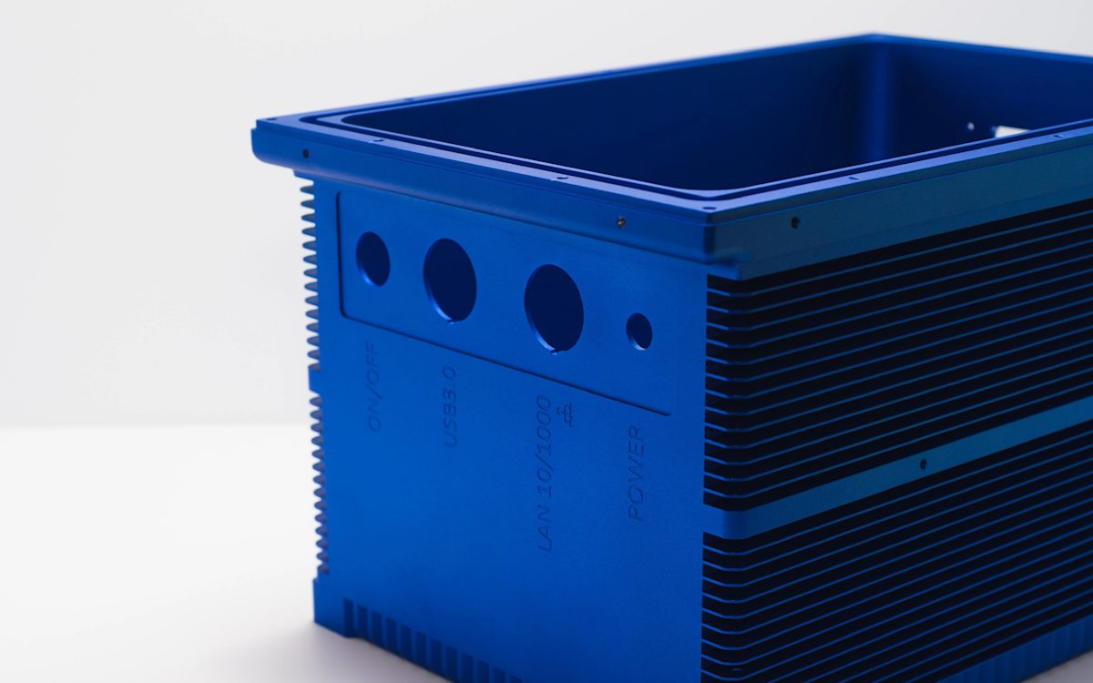
Electrical & electronic manufacturing
CNC machining has many applications in the electrical and electronic manufacturing industry: from the prototyping of PCBs to the manufacturing of enclosures.
TPAC, for example, used CNC machining to manufacture an enclosure for their high-power electronic sensing systems. Heat dissipation and electrical insulation were the main design requirements in this case. So, CNC machined anodized aluminum was ideal for their one-off custom enclosure.
Tooling & Industrial manufacturing
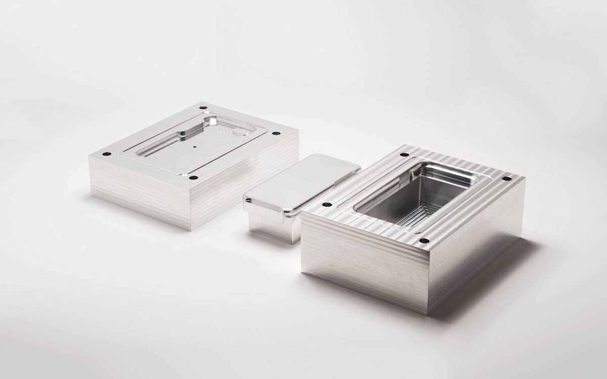
A very common industrial application of CNC machining is the fabrication of tooling for other processes. For example, the molds in Injection Molding are commonly CNC machined from aluminum or tool steel.
Precious Plastic, for instance, developed a system for the developing world that turns waste plastic into iPhone cases! For this purpose, they used a low-cost manual injection molder and custom CNC machined molds.
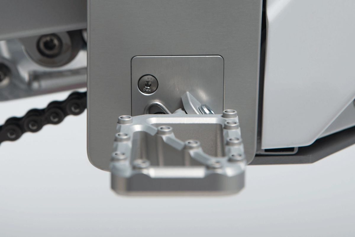
Sports & motorsports equipment
High-performance sports & motorsports manufacturers always try to increase the performance of their products by reducing their weight.
CAKE is a Swedish company that designed and developed the first off-road electric motorbike. Since it is the first of its kind, every single component of the motorbike was custom-made with CNC to achieve the intended level of quality and durability.
CNC machining vs. 3D printing
Both CNC machining and 3D printing are exceptional tools in the arsenal of an engineer. Their unique benefits make each more suitable for different situations though.
When choosing between CNC machining and 3D printing, there are a few simple guidelines that you can apply to the decision making process.
As a general rule of thumb parts with relatively simple geometries, that can be manufactured with limited effort through a subtractive process, should generally be CNC machined, especially when producing metal parts.
Choosing 3D printing over CNC machining makes sense when you need:
- A low-cost plastic prototype
- Parts with very complex geometry
- A turnaround time of 2-5 days
- Speciality materials
To summarize:
CNC offers greater dimensional accuracy and produces parts with better mechanical properties than 3D printing, but this usually comes at a higher cost for low volumes and with more design restrictions.
Scaling up production
If high volumes are needed (1,000’s or more), neither CNC machining nor 3D printing are likely to be suitable options. In these cases, forming technologies, such as investment casting or injection molding, are more economically viable due to the mechanisms of economies of scale.
For quick reference, use the table below. In this simplification, it is assumed that all technologies are able to produce the geometry of the part in question. When this is not the case, 3D printing is generally the preferred method of manufacturing.
| No. of Parts | Plastic | Metal |
|---|---|---|
| 1-10 | 3D printing | CNC machining (consider 3D printing) |
| 10-100 | 3D printing and CNC machining | CNC machining |
| 100-1000 | CNC machining (consider Injection molding) | CNC machining (consider Investment casting) |
| 1000+ | Injection molding | Investment or Die casting |
Part 2
Design for CNC machining
In less than 15 minutes, you will learn all you need to know to design parts optimized for CNC machining: from Design for Machinability rules to cost reduction tips and from material selection guidelines to surface finishing recommendations.
CNC machining design restrictions
The design restrictions in CNC machining are a natural result of the mechanics of the cutting process and in particular:
Tool geometry
Most CNC machining cutting tools have a cylindrical shape with a flat or spherical end, restricting the part geometries that can be produced.
For instance, the internal vertical corners of a CNC part will always have a radius, no matter how small a cutting tool is used.

Tool access
Surfaces that cannot be reached by the cutting tool, cannot be CNC machined.
This prohibits, for example, the fabrication of parts with internal ‘hidden’ geometries, and puts a limit to the maximum depth of an undercut.

Workpiece stiffness
Due to the cutting forces and the temperatures developed during machining, it is possible for the workpiece to deform or vibrate.
This limits, for example, the minimum wall thickness that a CNC machined part can have and the maximum aspect ratio of tall features.
Tool stiffness
Like the workpiece, the cutting tool can also deflect or vibrate during machining. This results in looser tolerances and even tool breakage.
The effect becomes more prominent when the ratio of length-to-diameter of the cutting tool increases and is the reason why deep cavities cannot be easily CNC machined.
Workholding
The geometry of a part determines the way it will be held on the CNC machine and the number of setups required. This has an impact on the cost, but also the accuracy of a part.
For example, manual repositioning introduces a small, but not negligible, positional error. This a key benefit of 5-axis versus 3-axis CNC machining.

Design rules for CNC machining
In the table below, we summarise how these restrictions translate into actionable design rules.
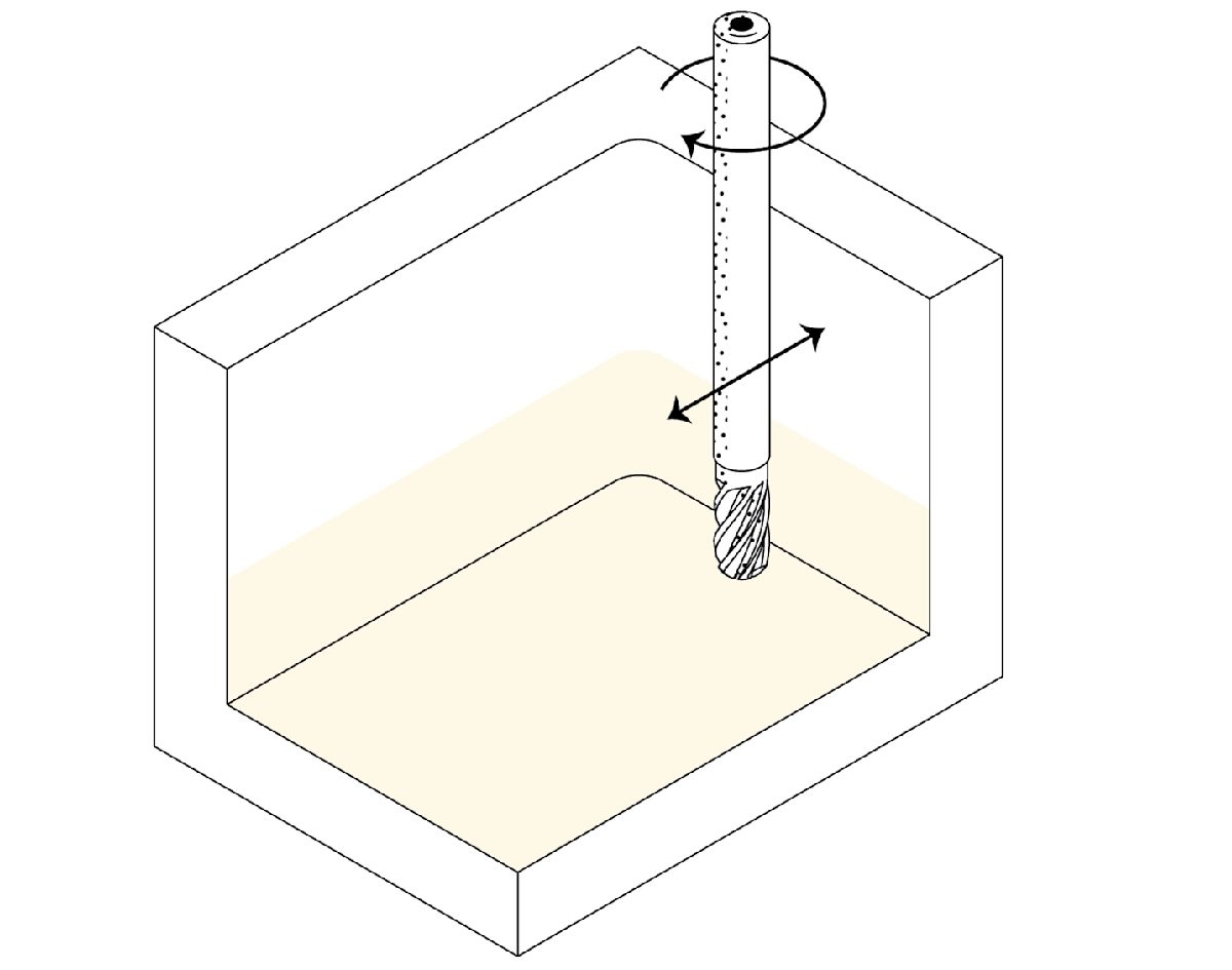
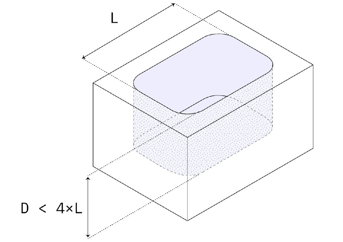
Cavities & pockets
Recommended depth: 4 x cavity width
Feasible depth: 10 x tool diameter or 25 cm (10’’)
Deeper cavities need to be machined with cutting tools with larger diameter affecting the fillets of the internal edges.
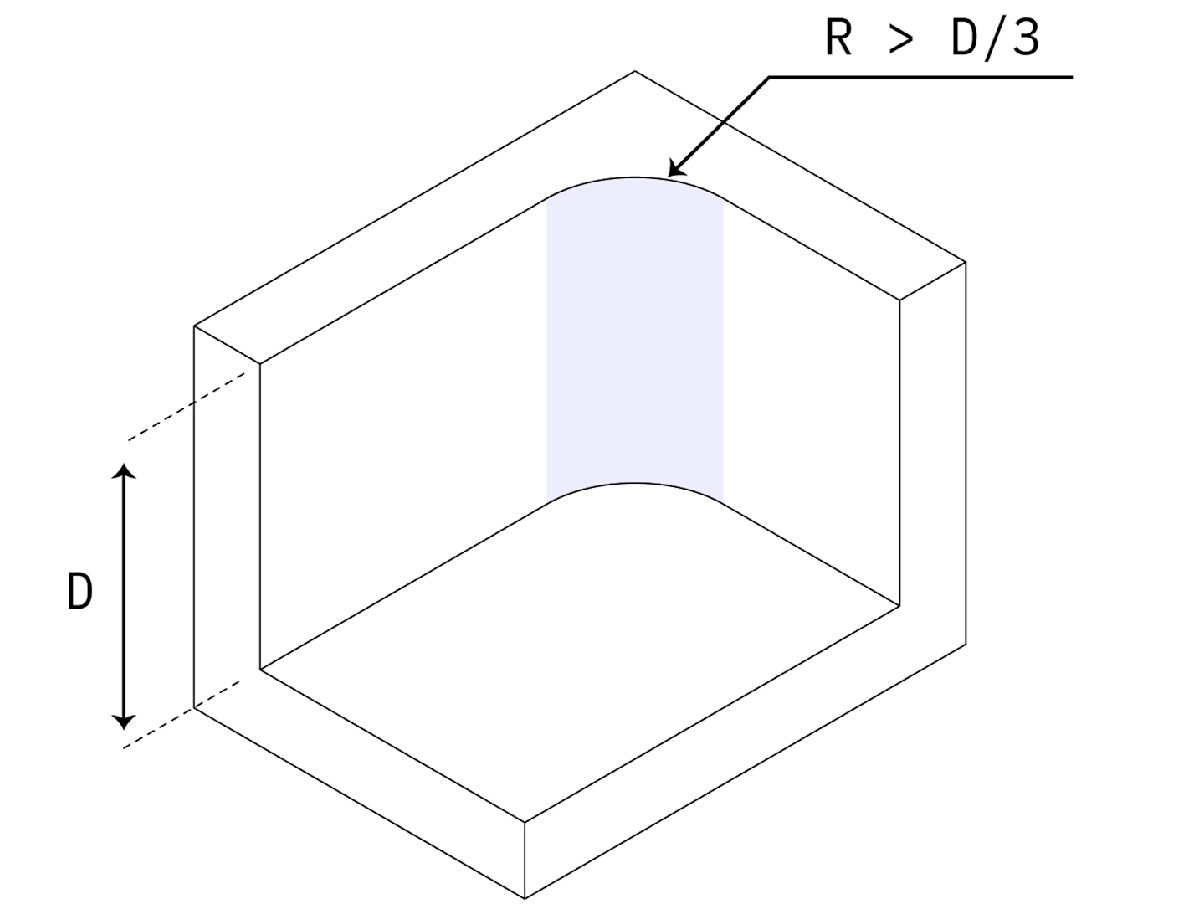
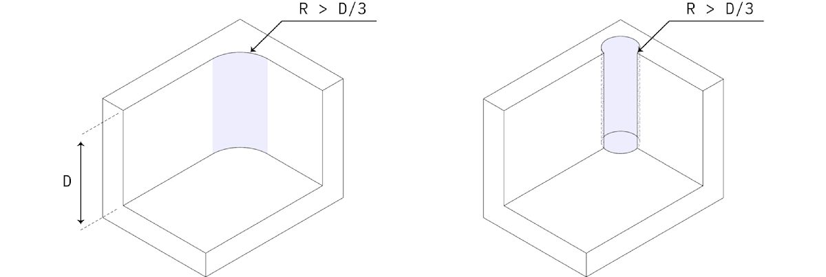
Internal edges
Recommended: larger than ⅓ x cavity depth
For internal vertical edges, the larger the fillet the better.
Edges on the floor of a cavity should be either sharp or have a 0.1 mm or 1 mm radius.
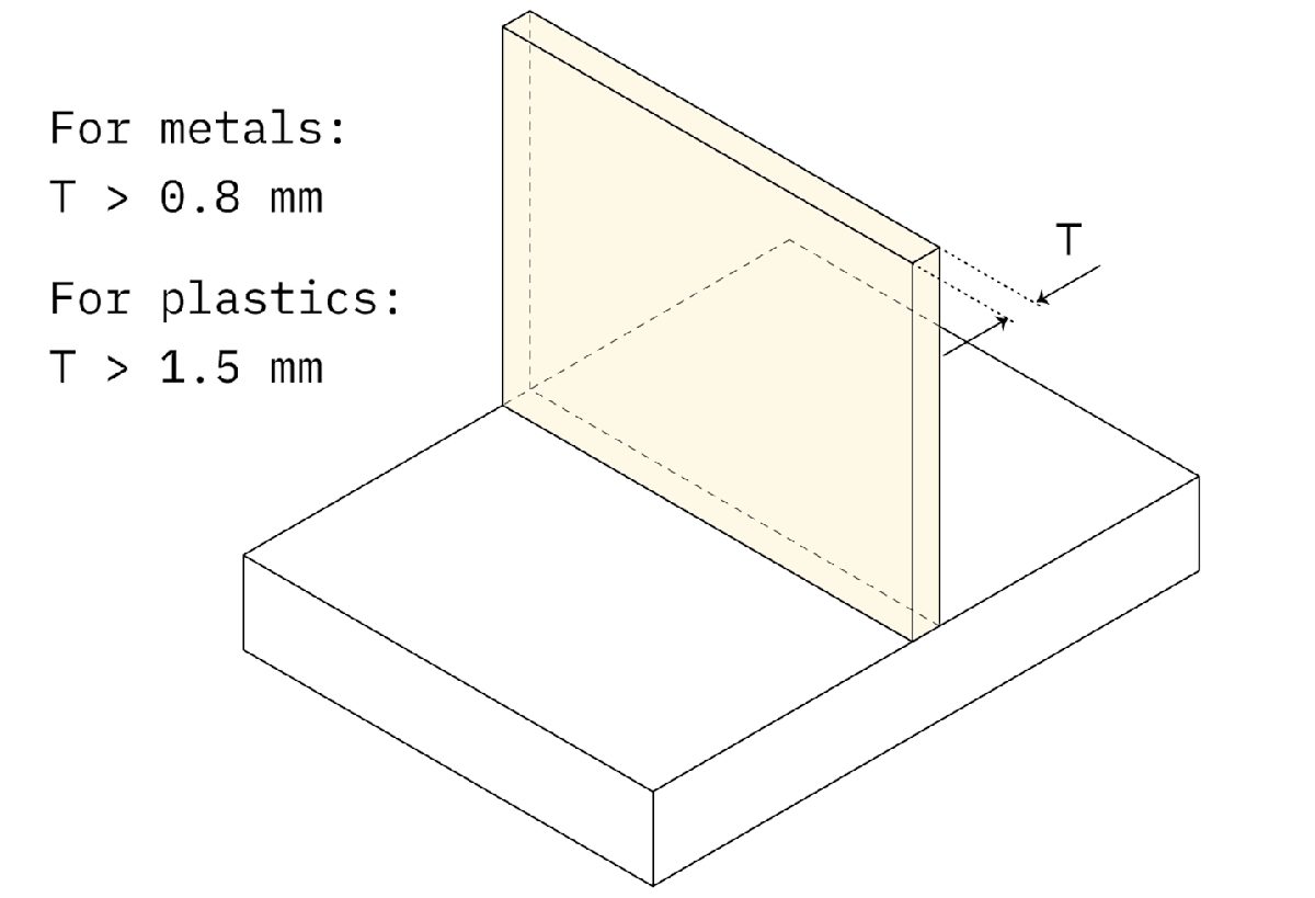
Minimum wall thickness
Recommended: 0.8 mm (for metals)
Feasible: 0.5 mm
Recommended: 1.5 mm (for plastics)
Feasible: 1.0 mm
Decreasing the wall thickness reduces the stiffness of the workpiece, increasing vibrations and lowering the achievable tolerances.
Plastics are especially prone to warping and thermal softening, so a larger minimum wall thickness is necessary.
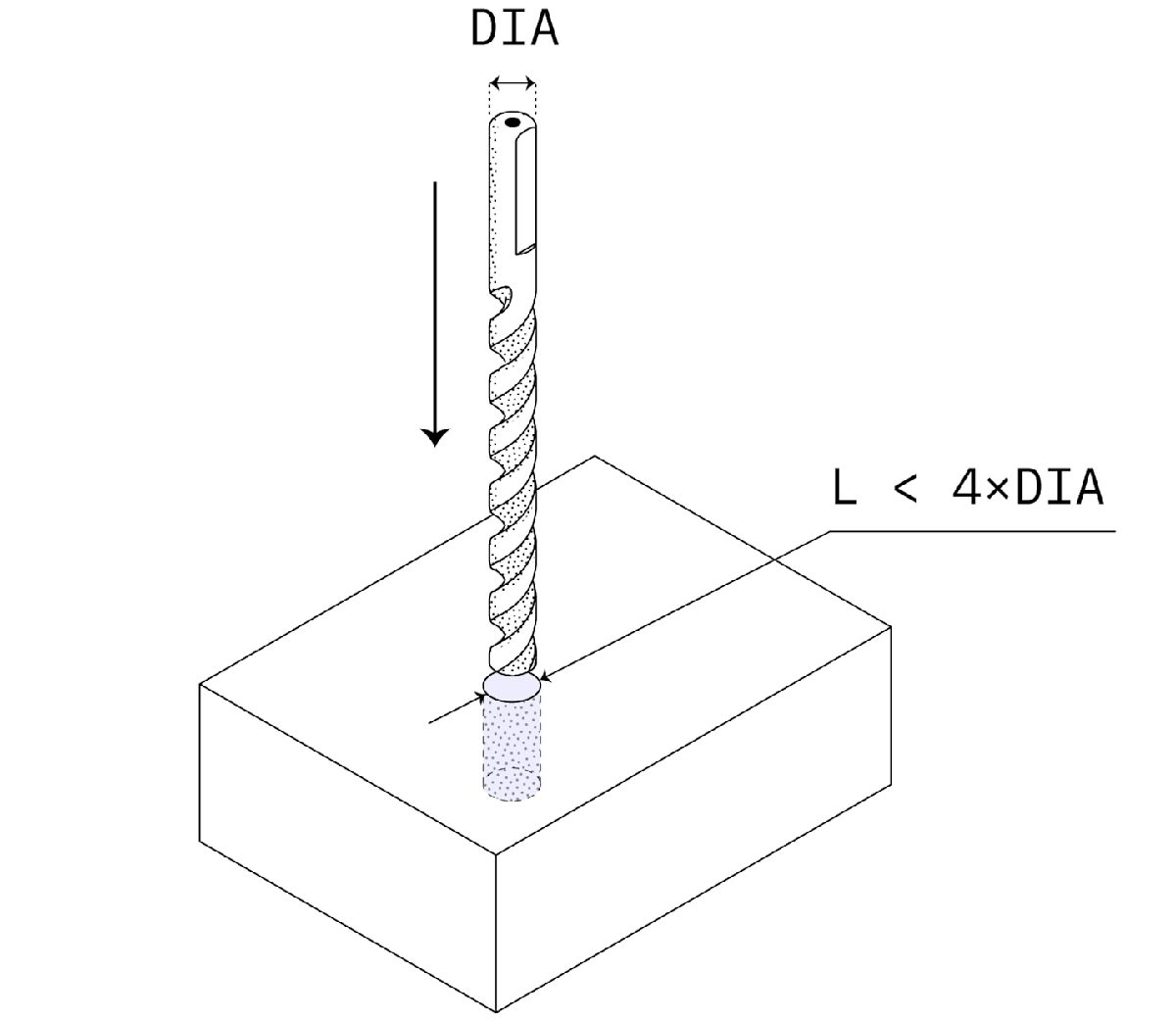
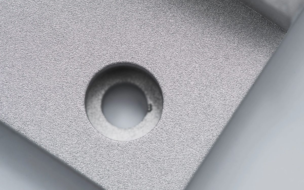
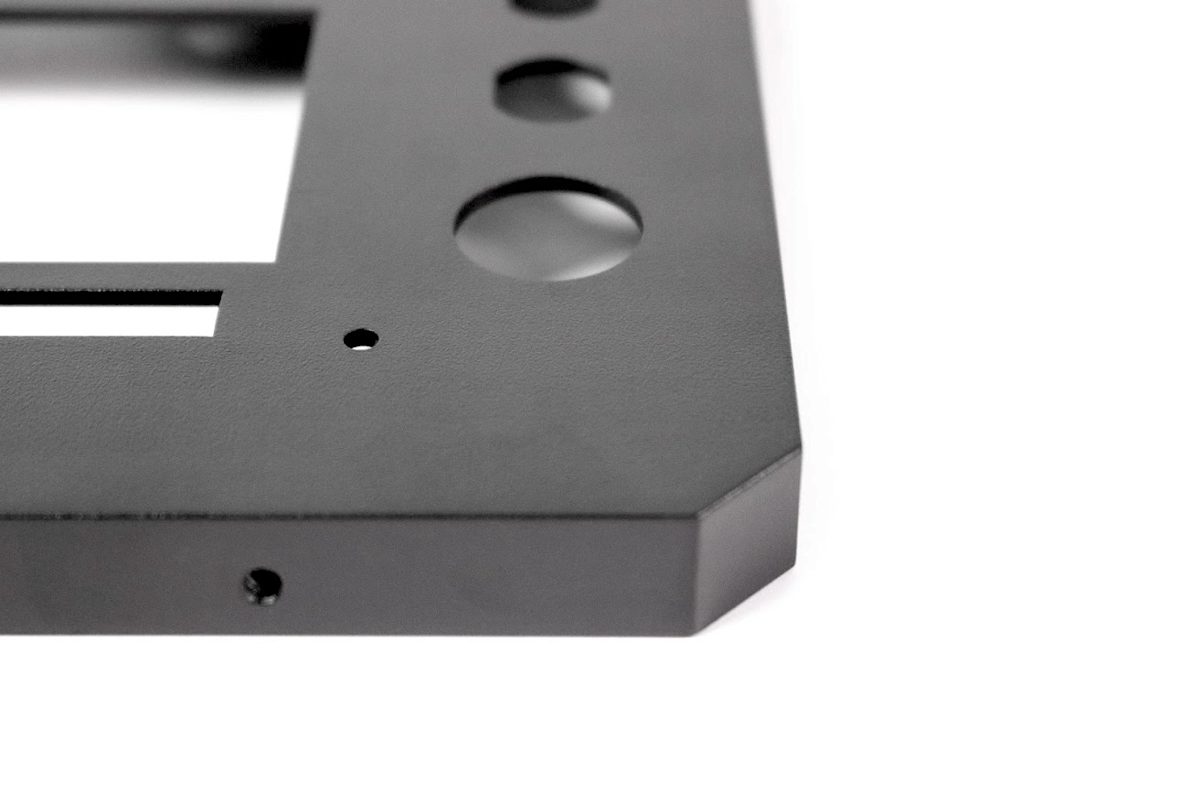
Holes
Recommended diameter: standard drill bit sizes
Recommended depth: 4 x nominal diameter
Max. depth: 10 x nominal diameter
Holes with standard diameter are preferred, as they can be machined with a standard drill bit. Blind holes machined with a drill will have a conical floor.
Holes with non-standard diameter will be machined with an end mill tool and should be treated as cavities (see previous rule). Blind holes machined with an end mill tool will be flat.
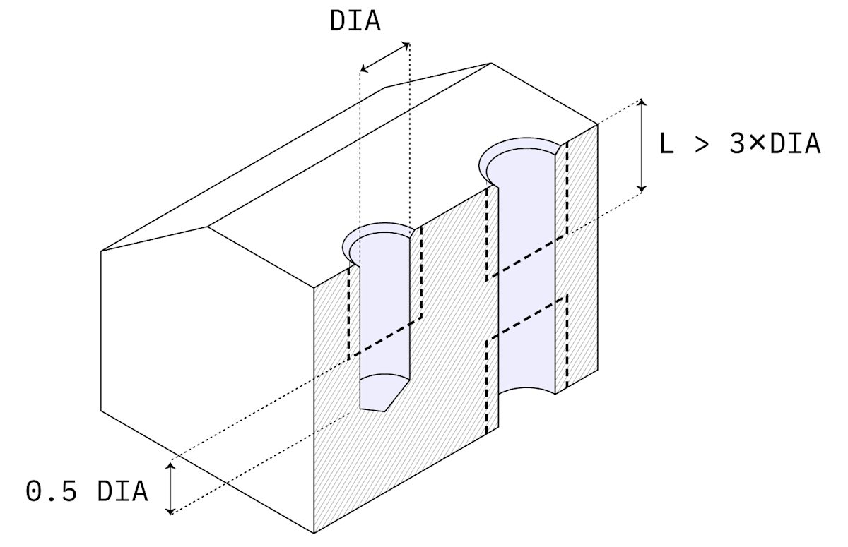
Threads
Recommended length: 3 x nominal diameter
Recommended size: M6 or larger
Feasible size: M2
Choose the largest thread possible, as they are easier to machine. Threads longer than 3 times the nominal diameter are unnecessary.
Always design threads as cosmetic in your CAD package and include a technical drawing to your order.
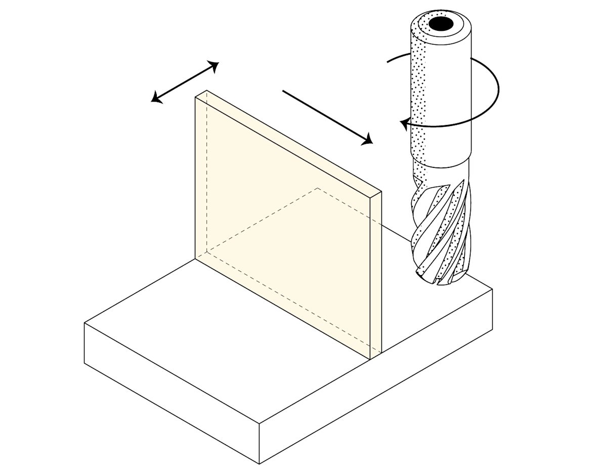
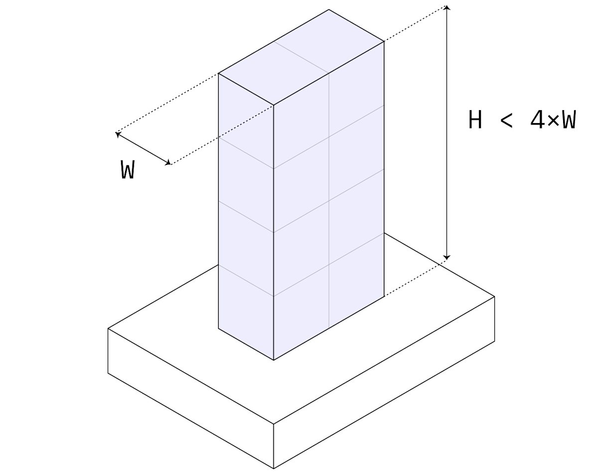
Tall features
Recommended max. ratio: height / width < 4
Tall features are difficult to machine accurately, as they are prone to vibrations. Consider the overall geometry of the part: rotating the part by 90° degrees during machining changes the aspect ratio.
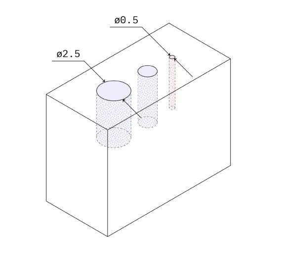
Small features
Recommended: 2.5 mm (0.100’')
Feasible: 0.50 mm (.020’’)
Cavities and holes down to 2.5 mm (0.1’’) can be CNC machined with standard cutting tools. Anything below this limit is considered micro-machining and must be avoided unless necessary.
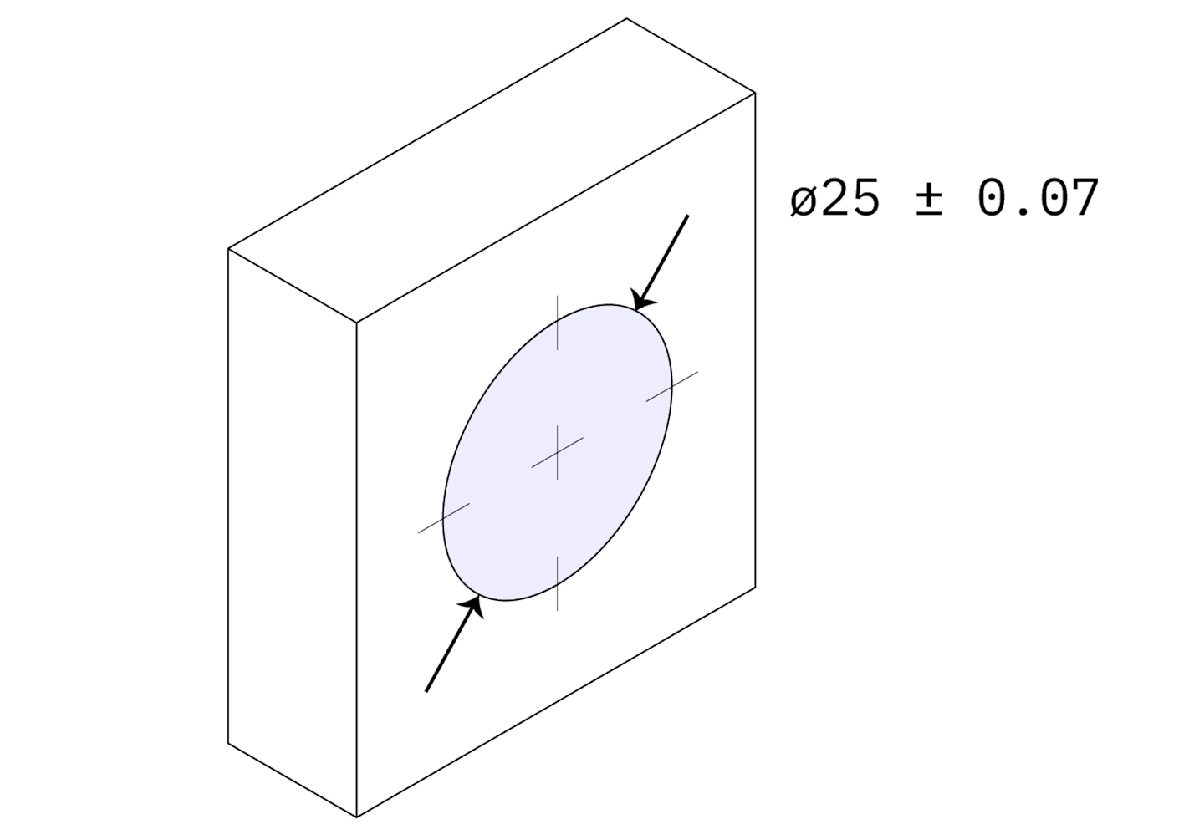
Tolerances
Standard: ± 0.125 mm (.005’')
Feasible: ± 0.025 mm (.001’’)
Tolerances (unilateral, bilateral, interference or geometric) should be defined on all critical features, but DO NOT over-tolerance.
If no tolerance is specified in the technical drawing, then the standard ± 0.125 mm will be held.
Maximum part size
CNC milling: 400 x 250 x 150 mm (typically)
CNC turning: Ø 500 mm x 1000 mm (typically)
Very large CNC machines can produce parts with dimensions up to 2000 x 800 x 1000 mm ( 78’’ x 32’’ x 40’’).
5-axis CNC machining systems typically have a smaller build volume.
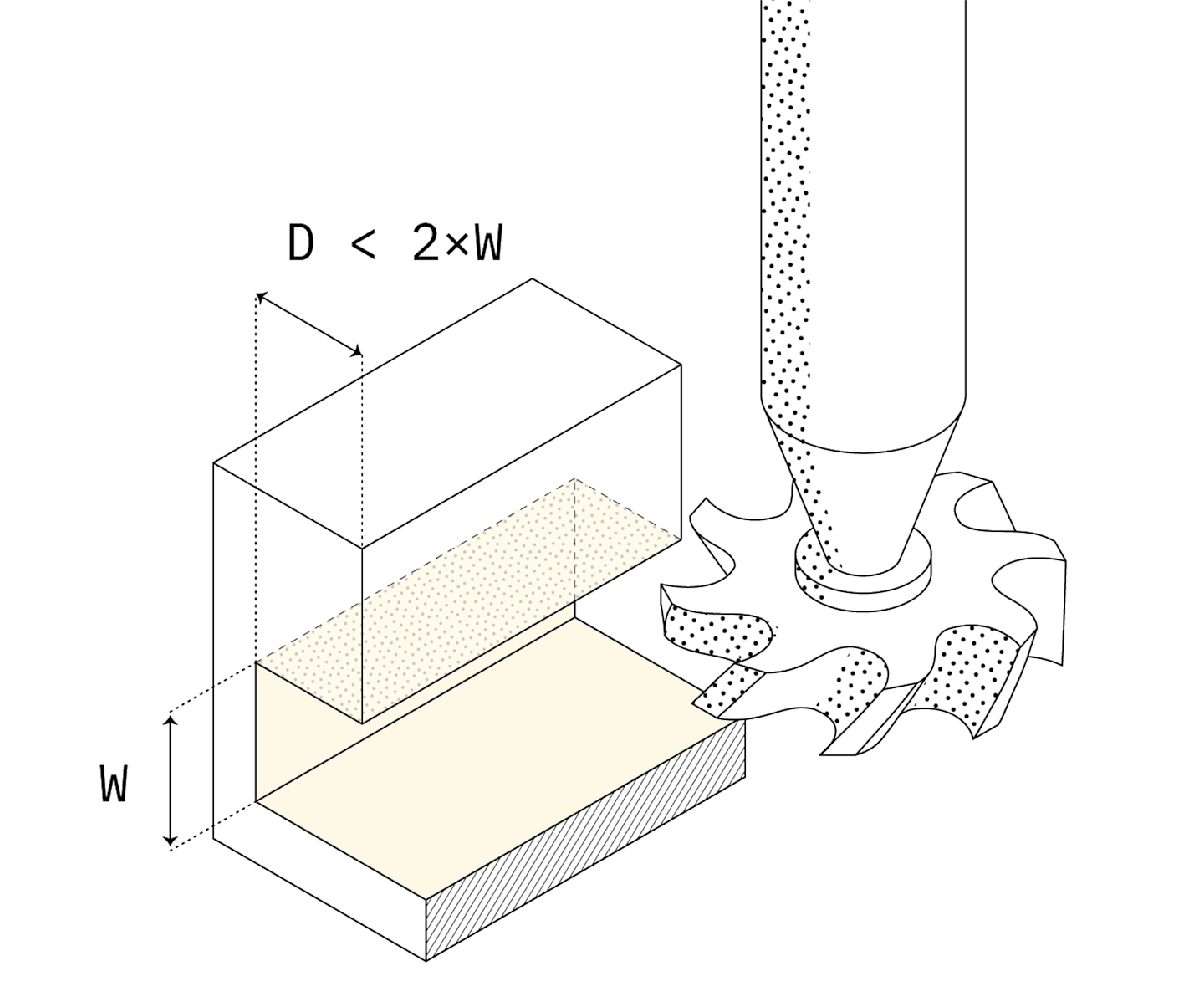
Designing undercuts
Undercuts are features that cannot be machined with standard tools, no matter how the part is rotated, because the cutting tools cannot access all surfaces. If square aluminum extrusions were manufactured with CNC machining, then their grooves would be considered undercuts.
Undercuts can be machined using special T-shaped, V-shaped or lollipop-shaped cutting tools if designed correctly.
Here are some practical guidelines to help you get started with designing undercuts.
Undercut dimensions
Recommended width: 3 mm (1/8’’) to 40 mm (1 ½’')
Max. Depth: 2x width
Design undercuts with a width of whole millimeter increments or a standard inch fraction. For undercuts with non-standard dimensions, a custom cutting tool must be created.
The standard tools have a cutting depth of approximately two times their width. This limits the achievable depth.
Undercut clearance
Recommended min. clearance: 4x depth
For undercuts on internal faces, add enough clearance between the opposing walls to ensures tool access.

Part 3
Materials for CNC machining
CNC machining can be used with a very wide range of engineering metals & plastics.
In this section, you will learn more about the key characteristics of the most popular materials. We will also examine the most common finishes that are applied to CNC machined parts.
Material choices
Selecting the right material is a crucial step in the design process. The optimal material option is highly dependent on your specific use case and requirements.
Since almost every material with sufficient hardness can be machined, CNC offers a very large range of material options to choose from. For engineering applications, metals and plastics are most relevant and will be the focus of this section.
Surface finishes can also alter the properties of CNC machined parts and we will examine them below.
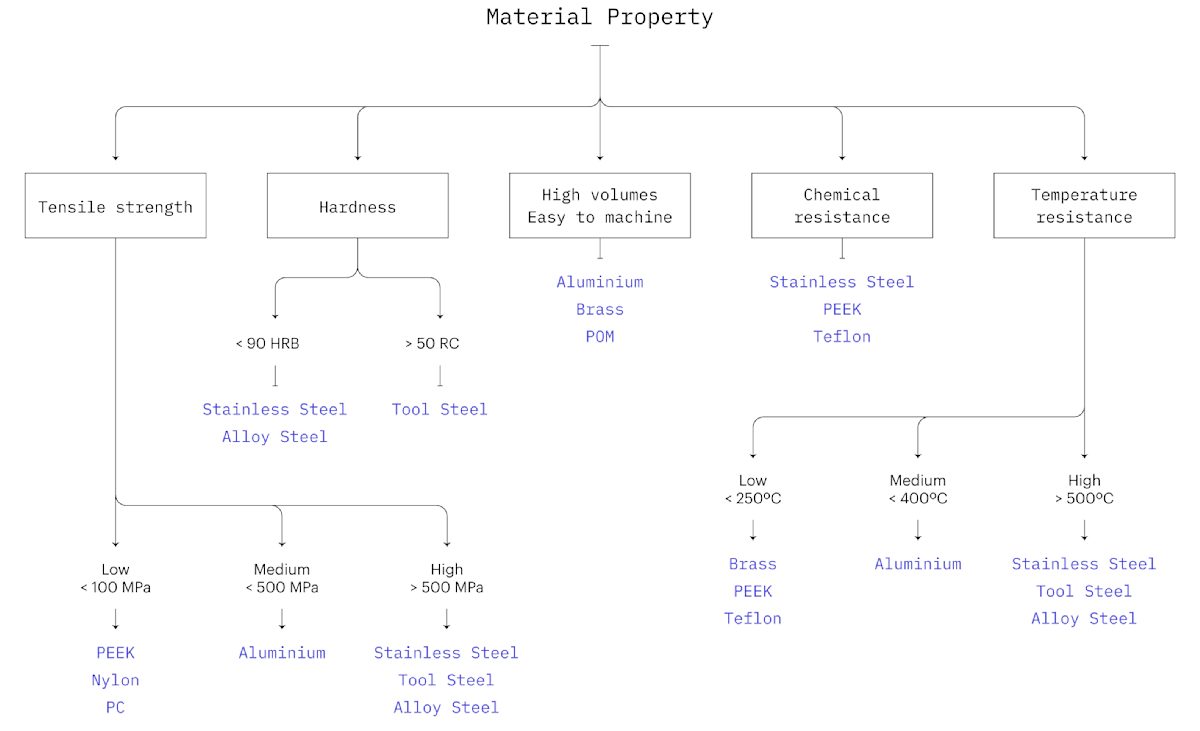
To get started, take a look at this decision tree. It contains high-level material recommendations that cover the most common design requirements.
Metals
CNC machining is primarily used with metals and metal alloys. Metal can be used for both the manufacturing of custom one-off parts and prototypes and for low-to-medium batch production. Aluminum 6061 is by far the most used material in CNC machining.
Plastics
Plastics are lightweight materials with a wide range of physical properties. They are often used for their chemical resistance and electrical insulation properties. Plastics are commonly CNC machined for prototyping purposes prior to Injection Molding.
Surface finishes
Surface finishes are applied after machining and can change the appearance, surface roughness, hardness and chemical resistance of the produced parts. Below is a quick summary of the most common finishes for CNC.
Explore the full range of finishes available on Protolabs Network →
As-machined
As-machined parts have the tightest tolerances, as no extra operations are performed on them. Marks following the path of the cutting tool are visible though.
The standard surface roughness of as-machined parts is 3.2 μm (125 μin) and can be reduced to down to 0.4 μm (16 μin) with further operations.
Extra cost: None
Bead blasting
Bead blasting adds a uniform matte or satin surface finish on a machined part, removing all tool marks.
Bead blasting is mainly used for aesthetic purposes, as the resulting surface roughness is not guaranteed. Critical surfaces or features (like holes) can be masked to avoid any dimensional change.
Extra cost: $
Anodizing (clear or colored)
Anodizing adds a thin, hard, non-conductive ceramic coating on the surface of aluminum parts, increasing their corrosion and wear resistance.
Critical areas can be masked to retain their tight tolerances. Anodized parts can be dyed producing a smooth aesthetically pleasing surface.
Cost: $$
Hardcoat anodizing
Hardcoat anodizing produces a thicker, high-density ceramic coating that provides excellent corrosion and wear resistance.
Hardcoat anodizing is suitable for functional applications. The typical coating thickness is 50 μm and usually, no color is applied. Critical areas can be masked to retain their tight tolerances.
Extra cost: $$$
Powder coating
Powder coating adds a thin layer of strong, wear and corrosion resistant protective polymer paint on the surface of a part.
It can be applied to parts of any material and is available in many colors.
Extra cost: $$
Silk screening
Silk screening is an inexpensive way to print text or logos on the surface of CNC machined parts for aesthetic purposes.
It can be used in addition to other finishes (for example, anodizing). The print can be applied only to the external surfaces of a part.
Extra cost: $
Part 4
Cost reduction tips
Learn more about what affects the costs in CNC machining. Use these three actionable design tips to cut the price in half and you keep your project on budget.
Tips to keep your CNC project on budget
The cost of CNC machined parts depends on the following:
- Machining time & model complexity: The more complex the geometry of a part is, the longer it takes to machine and the more expensive it will be.
- Start-up costs: These are related to CAD file preparation and process planning. They are significant for smaller volumes but are fixed. There is an opportunity to reduce the unit price by taking advantage of economies of scale.
- Material cost & finishes: The cost of the bulk material and the ease with which that material can be machined greatly affect the overall cost.
As a rule of thumb:
To minimize the cost of CNC machined parts, stick to designs with simple geometries and standardized features.
In the next sections, we re-examine some of the design rules we visited previously with cost-reduction in mind. With these 3 design tips, you can drastically reduce the cost of your CNC machined parts.
Learn 11 more tips to further reduce the cost of your CNC parts →
Tip #1: Increase the size of all fillets or add undercuts to sharp edges
To reduce machining times, add a fillet that is as large as possible to all internal (and external) vertical edges. This way a larger tool can be used, removing more material with each cut, and a circular toolpath can be followed, cutting each corner at a higher speed.
When a 90° internal edge is needed, reducing the radius will not do the job. In these cases, use an undercut instead (see above).
To minimize cost:
- Add a radius that is slightly larger than 1/3 of the depth of the cavity.
- Add a small fillet also to external edges.
- Use undercuts when a 90° internal corner is required.
Pro tip: Use the same radius for all edges to save time on tool changes.
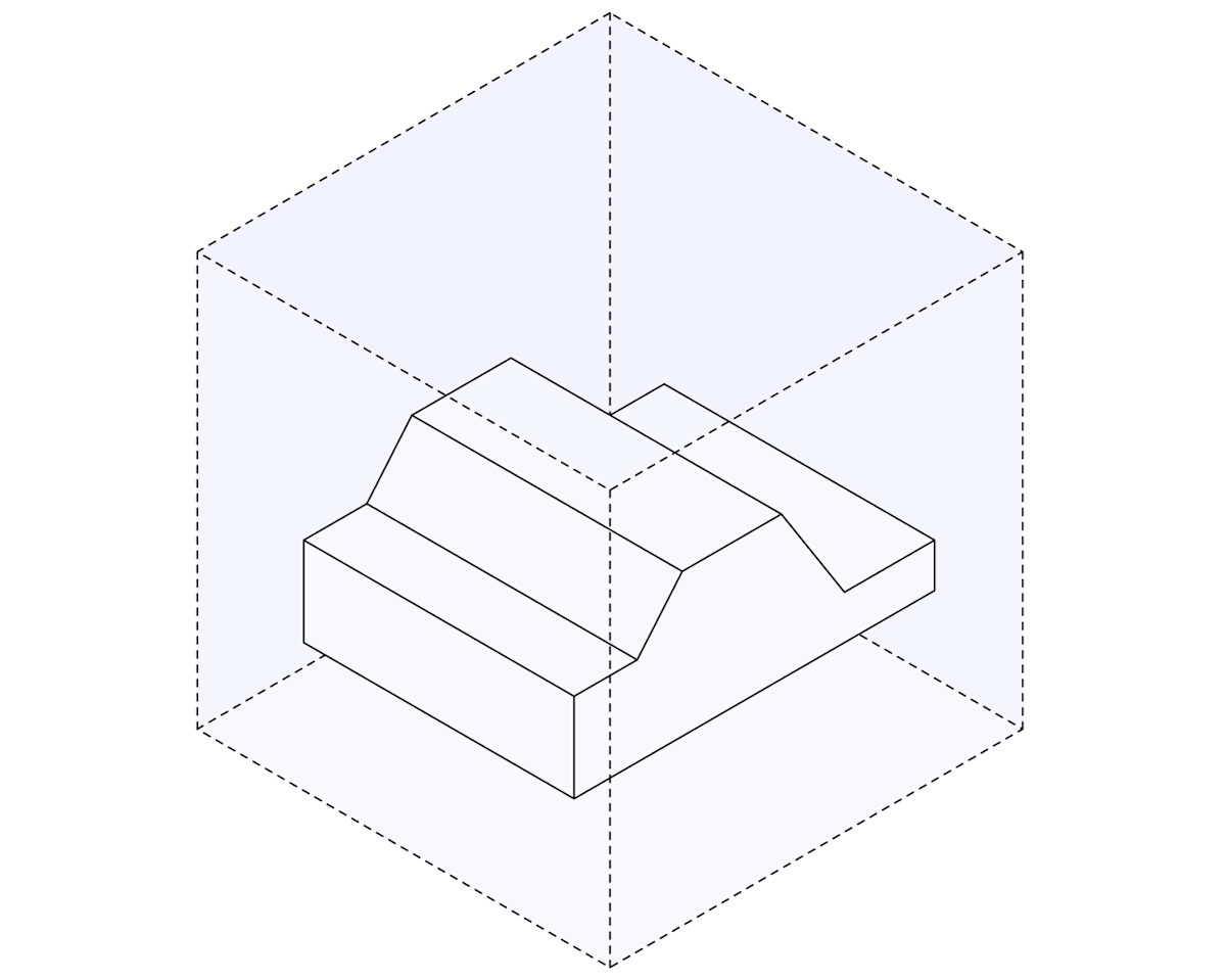
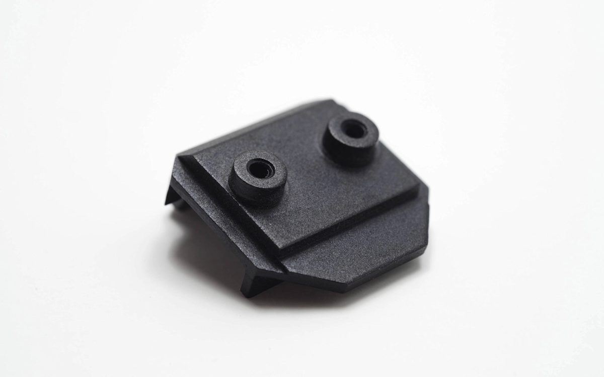
Tip #2: Minimize the number of machine orientations
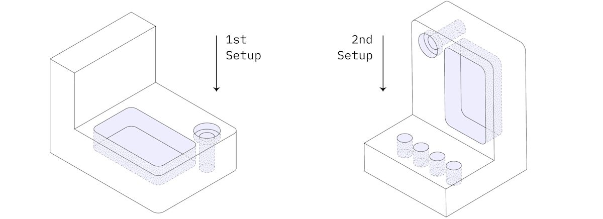
The part above requires at least two machine setups in a 3-axis CNC mill. After the features on one side are machined, the workpiece is rotated manually. This requires manual labor increasing costs.
Alternatively, a multi-axis CNC machines can be used. This also increases the machining costs though by about 60 to 100%.
To minimize cost:
- Design parts that can be machined in one or two setups in a 3-axis CNC mill.
- If this is not possible, consider splitting the part into multiple geometries that can be machined in one setup and assembled later.
Tip #3: Consider the cost of the material
Here is a table that summarizes the cost of the same part CNC machined in some of the most common materials. Each dollar sign indicates approximately a 25% price increase.
| Cost | Metals | Cost | Plastics |
|---|---|---|---|
| $ | Aluminum 6061 | $ | POM (Delrin) |
| $$ | Alloy steel 4140 | $$$ | ABS |
| $$ | Aluminum 7075 | $$$ | Nylon (PA 6) |
| $$$ | Brass C360 | $$$ | Polycarbonate (PC) |
| $$$$ | Stainless steel 304 | $$$$ | PEEK |
It is obvious that selecting a material with physical properties that surpass the requirements of your application can quickly and unnecessarily increase the cost of your CNC machined parts.
To minimize cost:
- Select the material with the lowest cost that has properties that fulfill your design requirements.
- Use online instant quoting to get quick feedback on the price of each material.
Part 5
Start CNC machining
With your parts designed and optimized for CNC machining, it is time to start thinking about manufacturing. In this section, we walk you through the 3 simple steps needed to manufacture custom parts with CNC machining.
Step 1: Export your design to a CNC-compatible CAD file format
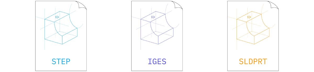
The file formats predominantly used in CNC machining are STEP and IGES. These formats are open-source, standardized and can be used across platforms.
For best results:
Export your designs directly from your native CAD software into the STEP file format.
On Protolabs Network, you can also upload files and get an instant quote for file formats used in your the native CAD software, including SLDPRT, 3DM, IPT, SAT and X_T.
Step 2: Prepare a technical drawing

A technical drawing is not always required for machining parts with CNC. Yet it is recommended to include one in your order as it has information that is not presented in a STEP file.
A technical drawing is required in the following situations:
- When your design contain threads
- When any tolerances are specified
- When certain surfaces need a different finishing
Learn how to correctly prepare a technical drawing for CNC →
Step 3: Get an instant quote & start manufacturing
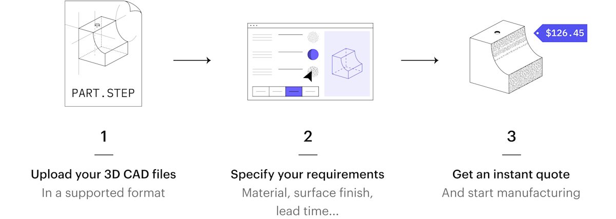
With Protolabs Network, outsourcing parts for CNC machining is easy, fast and highly price-competitive.
By combining a network of manufacturing services with our smart sourcing engine, you can instantly access readily available production capacity for the best possible quotes and lead times.
When you upload your parts to Protolabs Network, our automated Design for Machinability analysis will detect any potential design issues before production begins and will give you an instant quote, based on our machine learning algorithm.
This way you can be sure that you always receive the best price in the market at the fastest turnaround times for your CNC machining parts!
Part 6
Useful resources
In this guide we touched upon all you need to get you started with CNC machining. But there is plenty more to learn.
Below we list the best and most useful resources on CNC machining and other digital manufacturing technologies for those who want to delve deeper.
Knowledge Base
In this guide, we touched upon all you need to get you started with creating custom parts with CNC machining.
There is plenty more to learn about CNC machining in our Knowledge Base - a collection of technical articles on all manufacturing technologies, written by manufacturing experts and curated by Protolabs Network.
Here is a selection of our most popular articles on CNC machining:
Learn to machine
Are you looking to get your hands dirty with CNC machining? Then there are several ways to learn how to operate a CNC mill or CNC lathe.
-
Visit your local Fab Lab: Many Fablabs and Makerspaces have CNC milling capabilities and they will run courses on how to opperate them. Visit the official list of Fab Labs to find one near your area.
-
Find resources online: There are a lot of useful resources online to help you hone your CNC machining skills. The Titans of CNC Academy and NYCCNC are probably two of the best site to get you started.
-
Apply for an apprenticeship: Apprenticeships are probably the best way to kickstart your career as a CNC machinist. They are offered by established machine shops and many Universities.
Guides to other Manufacturing Technologies
Want to learn more about Digital Manufacturing? There are more technologies to explore: