


When to use 3D printing vs when to use injection molding
Learn what to consider when making a choice between 3D printing and injection molding, the benefits of each manufacturing method, and more.
Read articleIs 3D printing or CNC machining better for your custom part applications? Learn the practical differences between CNC machining and 3D printing and how to select the right technology for manufacturing prototypes, end-use parts and everything in between.
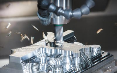
CNC machining is one of the most common subtractive manufacturing technologies. It uses a variety of rotating tools and cutters to transform a solid block of raw material—this is called a blank—into nearly finished components.
For both small one-off jobs and medium to high-volume production, CNC machining is one of the most popular methods of manufacturing. It offers excellent repeatability, high accuracy and a wide range of materials, post-processing options and surface finishes.
Did you know we offer local sourcing for CNC machining?

3D printing (3DP), which falls under the umbrella of additive manufacturing (AM), builds parts one layer at a time. 3D printing and other AM processes don’t require special tooling or fixtures, so the initial setup cost is minimal compared to CNC machining.

While the two technologies are quite different in how they work, there is a lot more overlap in how they’re applied than you might think, especially when it comes to prototypes and functional end-use parts (made from plastics and metals).
In this article, we cover the key technology considerations to help you choose the right technology for your custom part needs.
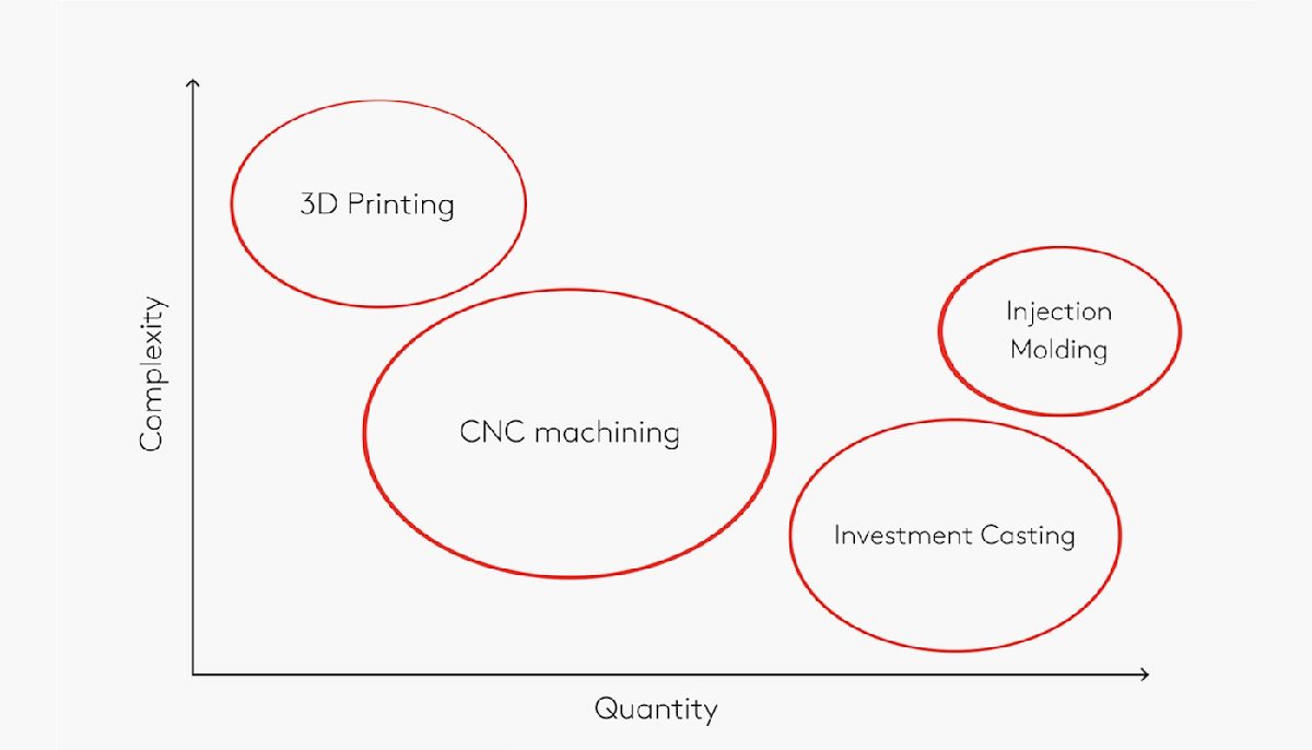
There are a ton of factors to consider when choosing the optimal manufacturing technology for your specific applications. Luckily, we’ve devised a few simple guidelines for selecting either 3D printing or CNC machining (or both in some cases).
As a rule of thumb, all parts that can be manufactured with limited effort through a subtractive process should generally be made with CNC machining.
CNC machining offers greater dimensional accuracy than 3D printing (this may change with further innovations to AM) and produces parts with better mechanical properties in all three dimensions. However, CNC machining usually comes with a higher price tag, especially with smaller volumes of parts.
3D printing is optimal in these situations (among many others):
When traditional methods are not able to produce the part efficiently or cost-effectively, or even at all. This occurs when you have highly complex, topology-optimized geometries, for example.
When a fast turnaround time is critical. 3D-printed parts can be delivered within 24 hours.
When you’re on a budget. 3D printing is generally cheaper than CNC machining for small volumes.
When you need a small number of identical parts (fewer than 10).
When your parts require materials that can’t be easily machined, like metal superalloys or flexible TPU.
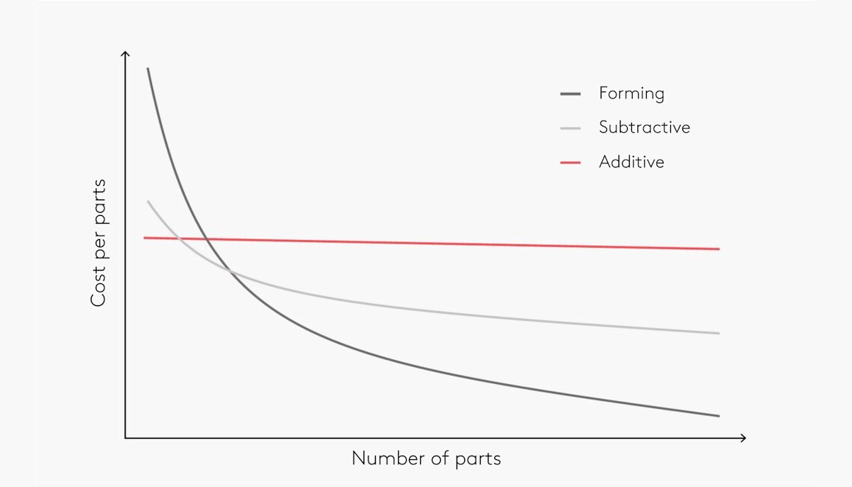
If you need to produce higher quantities of parts—hundreds or even thousands of individual components—then neither 3D printing or CNC machining may be the most viable option. Traditional forming technologies, like injection molding, are generally the most economical way to produce parts at scale.
The number of parts you plan to produce will play an important role in your final decision between 3D printing or CNC machining. In the table below, we break this down by the number of parts, materials and part geometry. Aside from our principal recommendations, we also include alternative options.
| Number of parts | 1-10 | 10-100 | 100-1000 | 1000+ |
|---|---|---|---|---|
| Plastic | 3D printing | 3D printing (consider CNC) | CNC machining (consider injection molding) | Inection molding |
| Metal | 3D printing & CNC machining* | CNC machining (consider 3D printing) | CNC machining (consider investment casting) | Investment or die casting |
| *this is highly dependent on part geometry |
CNC machining offers tight tolerance and excellent repeatability. Very large to very small parts can be CNC machined accurately. Thanks to the shape of most cutting tools, internal corners will always have a radius, but external surfaces can have sharp edges and can be machined very thin.
Each 3D printing system offers a different dimensional accuracy. Industrial machines can produce parts with very good tolerances. If tight clearances are required, the critical dimensions can be 3D printed oversized, and then machined during post-processing.
The minimum wall thickness of 3D printed parts is restricted by the size of the end effector (to the nozzle diameter in FDM or the laser spot size in SLS). Since parts are fabricated one layer at a time, layer lines might be visible, especially on curved surfaces. The maximum part size is relatively small, as 3D printing often requires pretty strict environmental control.
| Technology | Tolerance | Minimum wall thickness | Maximum part size |
|---|---|---|---|
| CNC machining | ± 0.025 - 0.125 mm* | 0.75 mm | Milling: 2000 x 800 x 1000 mm Lathe: Ø 500 mm |
| SLS | ± 0.300 mm | 0.7 - 1.0 mm | 300 x 300 x 300 mm |
| FDM | Desktop: ± 0.500 mm Industrial: ± 0.200 mm | 0.8 - 1.0 mm | Desktop: 200 x 200 x 200 mm Industrial: 900 x 600 x 900 mm |
| SLM/DMLS | ± 0.100 mm | 0.40 mm | 230 x 150 x 150 mm |
| Binder jetting | ± 0.200 mm | 2.0 mm | 380 x 355 x 735 mm |
| *According to the specified level of tolerance |
3D printing and CNC machining both work with metals and plastics, though the two technologies don’t manipulate these materials equally.
CNC machining is mainly used to produce parts from metal. As it’s quite flexible, you can also use the CNC process to manufacture parts from thermoplastics, acrylics, softwoods and hardwoods, modeling foams and machining wax.
Great mechanical and thermal properties with fully isotropic behavior
Dimensional restrictions from blank size (using a non-standard blank size will increase the manufacturing cost)
Plastics: ABS, Nylon, Polycarbonate, PEEK
Metals: Aluminum, stainless steel, titanium, brass
3D printing is predominantly used to create parts using thermoplastics and thermosets, though you can print metal parts with some technologies. Several 3D printers can produce parts from ceramics, wax, sand, composites and a growing roster of bio-materials.
Wide variety of materials with a wide range of physical properties
Materials that are difficult to machine (TPU and metal superalloys) can be 3D printed
Potentially lesser mechanical properties compared to CNC parts, as they are typically not fully isotropic
Part complexity is a major factor to consider when choosing between 3D printing and CNC machining. Both technologies have their share of design limitations, though CNC machines can produce far fewer geometries.
CNC machining involves several key design limitations, including tool access and clearances, hold or mount points, as well as the inability to machine square corners due to tool geometry. Some geometries are even impossible to manufacture with CNC, as the tools can’t access all surfaces of your part. This goes for 5-axis systems as well.
Most geometries require the operator to rotate the part so tools can access different sides and angles. Repositioning adds to the processing and labor time, and in some cases, jigs and fixtures are required. All of these factors will raise the final price of the part.
Compared to CNC, 3D printing can produce parts with very few geometric limitations. Support structures may be needed for processes like FDM, but a little extra post-processing doesn’t diminish the vast design freedom and capacity for complexity you get with 3D printing.
Plus, polymer-based powder bed fusion processes such as SLS and MJF can produce freeform, organic geometries without the need for support structures. The ability to produce highly complex geometries with relative ease is one of 3D printing’s key strengths.
It’s important to understand the workflows for both types of manufacturing processes discussed in this article. Let’s break down the workflows for 3D printing and CNC machining.
CNC manufacturing tends to be a labor-intensive process. With CNC, the machine operator will first have to decide upon tool selection, spindle speed, cutting path and potential part repositioning. The operator will have to manually set up the block in the machine, keeping all these factors in mind. As well, it will be essential to know whether the component will be ready after machining or whether you’ll need one or several post-processing steps. All of these considerations will affect the quality of the component as well as its build time.
With 3D printing, the operator will first prepare the digital file, choosing orientation and adding supports if necessary. Then the file will go to the machine, where the printer does all the building work with little to no human intervention. When printing is complete, the part will need to be cleaned and go through post-processing. These last steps are the most labor-intensive parts of the 3D printing manufacturing workflow.
There are many post-processing methods that can be applied to both 3D printing and CNC machining to improve the functional and cosmetic qualities of parts. Let’s cover the most common post-processing techniques.
CNC machining: Bead blasting, anodizing (Type II & Type III), powder coating
3D printing: Media blasting, sanding & polishing, micro-polishing, metal plating
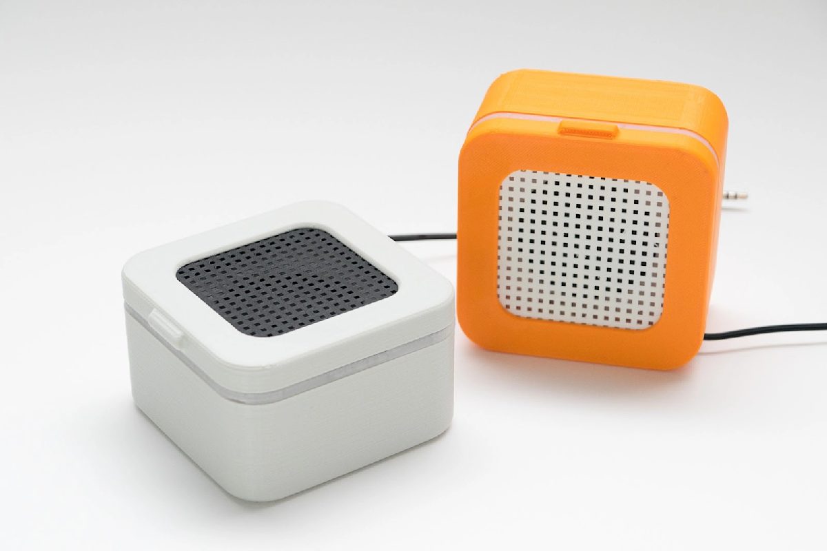
If you’re designing a new consumer electronics product, fabricating prototypes for the enclosure is a key step before you can start manufacturing at scale. Fast lead times and low cost are the main objectives for accelerating development time.
Enclosures for electronics often have snap fits, living hinges or other interlocking joints and fasteners. You can produce all of these features with FDM and SLS 3D printing or CNC machining.
CNC and SLS can be used to create high-accuracy and cosmetic prototypes, but FDM (we’re talking desktop here) has much shorter lead times and is cheaper. Since mechanical performance may not be the highest priority for this kind of project, the benefits of CNC and SLS are not usually worth the extra cost and time.
| Factor | CNC machining | Desktop FDM | SLS |
|---|---|---|---|
| Cost | $$ | $ | $$ |
| Common materials | ABS, Nylon | PLA, ABS, Nylon | Nylon |
| Lead time | 1-2 weeks | 1-3 days | Less than a week |
| Accuracy | ± 0.125 mm | ± 0.500 mm | ± 0.300 mm |
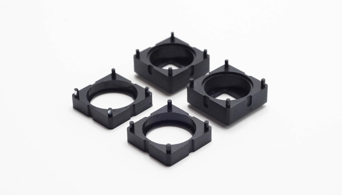
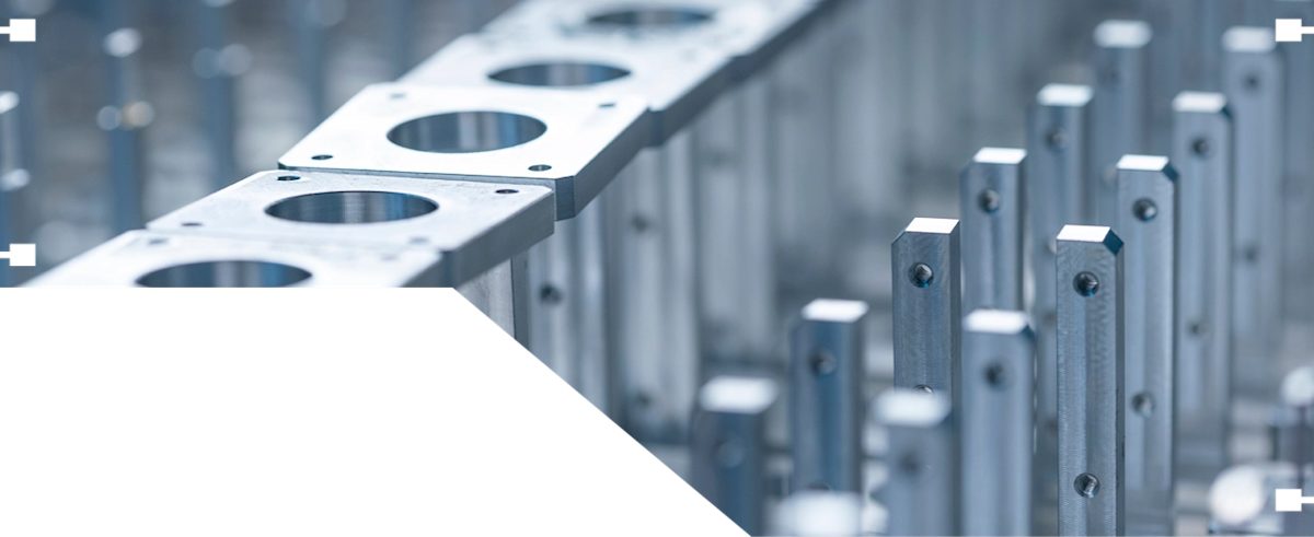
Metal brackets and other mechanical components can bear heavy loads and operate at more extreme temperatures. If you’re producing these kinds of parts, your main objectives will likely be good material properties and dimensional accuracy.
CNC machining is the best option in terms of accuracy, cost and mechanical accuracy if the geometry of your model is simple (like the components of the image above).
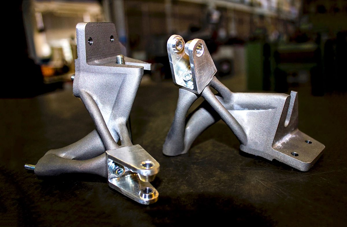
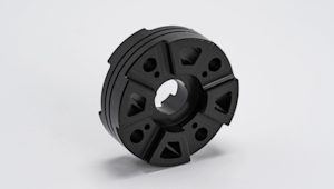
When the geometric complexity increases or when you need to use less common materials, you may want to consider metal 3D printing. Components optimized for weight and strength (like the brackets of the image below) have organic structures that are very difficult and costly to machine with CNC systems.
Of course, you can combine CNC machining and metal 3D printing to manufacture parts with organic shapes and very tight tolerances at critical locations on the components.
| Factor | CNC machining | CSLM/DMLS | Binder Jetting |
|---|---|---|---|
| Cost | $$ | $$$$ | $$$ |
| Common materials | Aluminum, stainless steel, brass | Stainless steel, aluminum, titanium, Inconel, cobalt-chrome | Stainless steel, Inconel, cobalt-chrome, Tungsten carbide |
| Accuracy | ± 0.025 mm | ± 0.100 mm | ± 0.200 mm |
| Mechanical properties | Very good | Very good | Good |
Selecting the right manufacturing technology for your custom parts may feel like an insurmountable challenge, but it doesn't have to. We’ve put together a few essential rules of thumb to follow if you’re facing this decision.
Choose CNC machining if you are producing parts in medium to high quantities (250-500 parts) that have relatively simple geometries
Choose 3D printing for lower quantities of parts—or single prototypes—and if your designs have complex geometries
When considering metals, CNC can be price competitive even for low quantities, but geometry limitations still apply
If you’re printing more than 500 parts or so, maybe consider other technologies like injection molding (or a mix of 3DP or CNC and a forming process)
Curious about the costs of 3D printing and CNC machining?
The short answer to this question is: it depends. CNC machines can produce parts with smoother surfaces than 3D-printed parts, and you probably want to go with CNC machining if you want your components to fit together with precision. 3D printing yields excellent parts for finish and fit, though the quality of both also depend on which type of 3D printer you’re using.
For many prototyping and functional applications, we recommend using industrial FDM and SLS if you’re printing plastic parts.
SLM/DMLS and Binder Jetting are the two best options for producing functional parts and prototypes from metal materials.
When it comes to cost and lead times (both essential in the prototyping phase of product development), 3D printing wins over CNC machining.
3D printing hasn’t replaced CNC machining, more traditional subtractive methods or injection molding yet, but additive technology is advancing rapidly. You can now 3D print parts from a wider variety of materials, including some metals. However, for many applications, CNC machining is the better option.

Learn what to consider when making a choice between 3D printing and injection molding, the benefits of each manufacturing method, and more.
Read article
Learn about the advantages and disadvantages of various methods of industrial 3D printing, materials that are commonly used, and more
Read article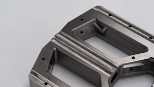
What is Delrin and why is it unique among the many manufacturing materials available? Delrin, or POM-H (homopolymer acetal), is used in CNC machining, 3D printing and injection molding to create durable, precise components. This article explores Delrin’s properties and how to get the most out of the material.
Read article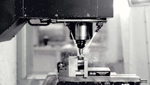
What is CNC milling and how does this subtractive manufacturing process work? This article explores how CNC milling machines work, what kinds of parts you can provide with milling and the best design practices for getting the most out of this type of CNC machining.
Read article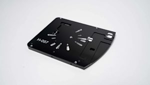
How do you add logos, lettering, serial numbers and other customized designs to your custom parts? Part marking is a cost-effective way to give parts those extra identifying and/or cosmetic details. Learn the common part marking techniques on the market today, including laser engraving and silk screening.
Read article
Multi Jet Fusion (MJF) is a 3D printing process for building prototyping and end-use parts fast. This article explains how MJF works and its main advantages.
Read article
Rapid prototyping uses 3D computer-aided design (CAD) and manufacturing processes to quickly develop 3D parts or assemblies for research and development and/or product testing.
Read article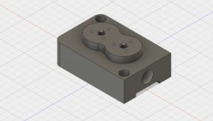
How do you prepare technical drawings for CNC machining and why are they important? Technical drawings are widely used in manufacturing to improve the communication of technical requirements between the designer and engineer and the manufacturer.
Read article
What is CNC machining and how does it work? Learn the basic principles and fundamental mechanics, as well as the key benefits and limitations, of this subtractive manufacturing process.
Read article
Use these conversion tables of standard drill bit sizes (metric, fractional inch, and wire gauge) common in CNC machining to reduce manufacturing costs from custom tooling.
Read article
In this introduction to Binder Jetting 3D printing, we cover the basic principles of the technology. After reading this article you will understand the fundamental mechanics of the Binder Jetting process and how these relate to its benefits and limitations.
Read article