snaok
1
Hi,
This is my first post here. I am trying to make a case for a raspberry pi model B (old) in blender 2.79b. I intend to use a printer at the local library which has a Maker bot replicator + (they use PLA).
So far I have read around and seen that I need to have the normal’s correct so that there is volume. I have looked around quite a bit but still have a lot of questions.
Should I use a Boolean modifier to add text to the case, or is there another way (maybe in a ?slicer program) like the Maker ware that the library has connected to the printer?
Can you create screw holes in the plastic or can you drive self tapping screws into the plastic without tearing it (PLA), or maybe using a drill bit?
The 3D Printing Addon has some tests that I don’t know how to adjust for the Maker bot replicator +. Where would I look on the Maker ware software for this info?
degenerate: zero edge faces, zero length edges

distorted: in degrees, non flat faces

thickness: relies on correct normals

edge sharp: in degrees

overhang: in degrees
Particularly thickness because I cannot finalize the design without knowing how thick to make the walls.
thanks for any help,
Hi, you asked a couple of questions so I’ll answer them to the best I can in order.
Yes, when modeling in bender you need to make sure the normals are facing the right way so that the model is solid on the inside and won’t confuse the slicer.
Not sure what you mean by boolean operator because it’s been ages since I last used blender but you should use whatever tool in blender you normally use to add text to models and it should be fine.
As for screws, in my experience, threads for screws have never worked for me on screws as small as the holes on the raspberry pi. Self-tapping screws could work but they could split the plastic as you said. If I were you I would use M3 screws and nuts or super glue.
I have not used Makerware in around 3 years so I have no idea what degenerate, distorted and edge sharp are but I believe thickness refers to the thickness of the perimeter wall of the part. In that case, this doesn’t actually refer to how thick the model is but the thickness of the solid outer wall of the part. In most slicers, this is measured in shells and I normally have it at 2 shells. Basically, the amount of solid outer layers before it prints the hollow infill. You don’t need to make the part the same thickness as the perimeter walls.
I not sure how well I explained this so feel free to ask any questions.
1 Like
snaok
3
So, the Makerware software is the slicer? So could I run through some kind of test with that software to see if it thinks the case will print properly?
They had it set on 2 shells, but I am not understanding I thought the walls would be solid, about 1mm or 2?
So with the m3 screws I would model a hexagonal hole and glue a nut in there?
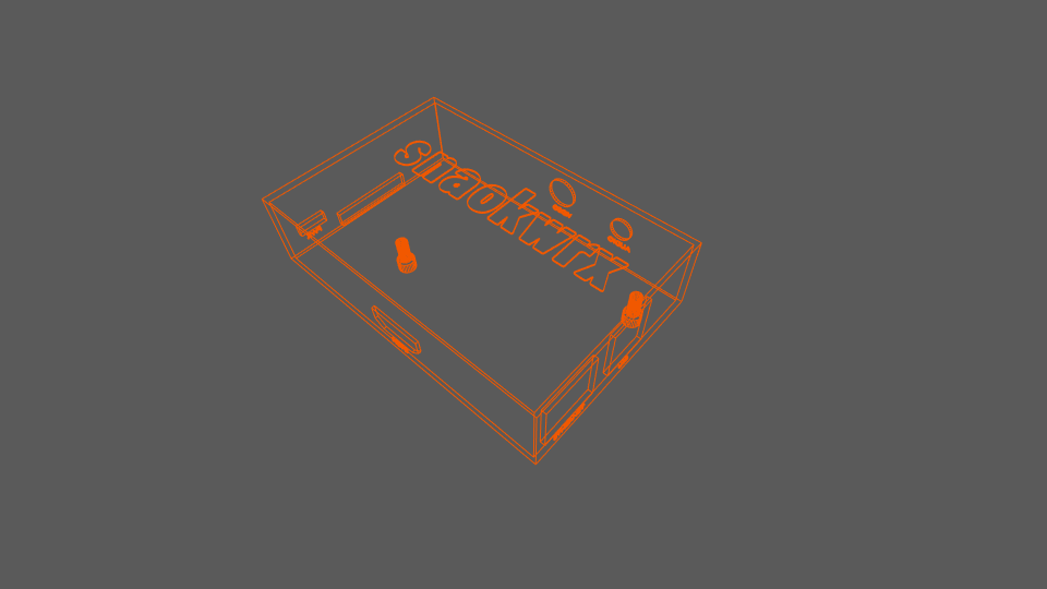
Just out of extra caution, this is what I get with the Boolean modifier after I cut the text. does this look feasible?
This was really helpful, thank you
Yes, Makerware is the slicer. You can use any slicer you want that supports export to .x3g files.
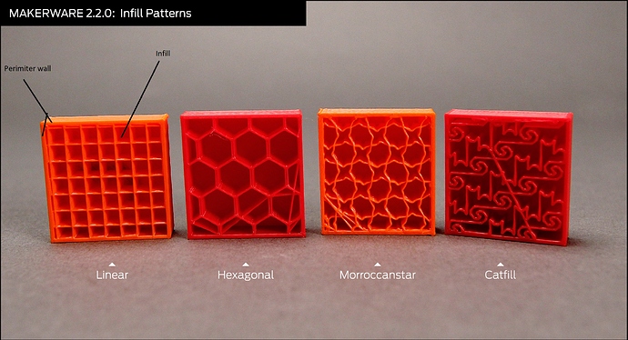
2 Shells just mean the printer prints 2 solid lines for each side of the wall between the perimeter walls is infill. This should be fine for making a case. To explain this better I will find a diagram and attach it. 3d prints are normally hollow on the inside with an infill structure like a honeycomb or linear box. This is done to reduce plastic use and print times. By default, it’s probably set to linear. This infill is surrounded by a thin wall which is the perimeter wall. More shells mean thicker outer wall not the thickness of your part. More or fewer shells dosn’t affect the dimensions of your part.
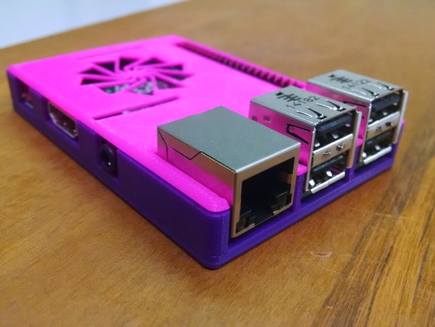
For M3 screws that’s one way of doing it. You could also have the holes go all the way through the part and have the nuts on the outside in a recess. I forgot to mention you could model pegs for the raspberry pi to sit on and have the lid hold it in place like this design.
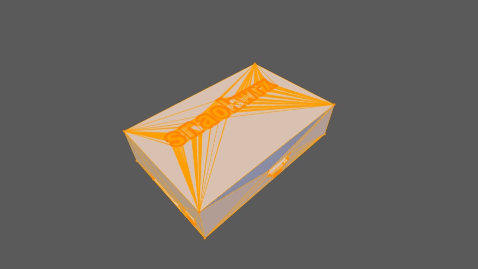
Form the picture I can’t really tell if it will print or not but I can’t see any obvious problems with it. if you want you can send me your file and I could slice it with Simplify 3d and see if anything wrong with it.
Also, it’s cool that your library has a 3d printer.
1 Like
snaok
5
Yeah, the library a couple of towns away has one. It is a nice thing.
I have to correct myself, its maker ware (maker bot print) from the notes I took.
The pins are what I had in mind, but I was thinking of using screws to hold the lid on. Maybe pins to hold the pi in place or something… actually I was thinking maybe some sort of snap,toggle thing. I have not really finished ironing out a lot of the details yet like I wanted the entire thing enclosed. Like the model I now have still has the lid connected, or part of the same mesh.
As far as sending you the model, thanks for the offer but I have to adjust what I am working with now that I’ve learned a bit. That’s good that you think there are no obvious problems, it just looks like a lot of edges/faces/vertices. I have to try and implement these new ideas into the model.
I have been reading up on the maker bot print software and it has a simulation feature that I will use (I think) next time the printer is available which looks like it will be next Wed.
That’s good there is a simulation feature. If not I found a website for you to simulate a print. You will just have to export it as a .gcode not .x3g to use it.
The extra faces and vertices are normal when working with text on a plane so there is nothing to be worried about there.
I hope I was able to help. Good luck with your project.