Hi,
If you’ve already mastered your SOLIDWORKS design skills, but want to level up your 3D printing ones to match, what follows is for you. Here’s a collection of tips on how to improve your SOLIDWORKS 3D CAD files for 3D printing, and how to go around the limitation of various technologies, so you can turn your designs into a reality! We’re gonna tackle things like settings optimisation, 3D printing with various materials, how to save costs and a bit more, so read on:
1. Optimising Your Print
Resolution
The resolution of a 3D print, or simply put the layers’ thickness, goes hand-in-hand with the layer height setting, which is measured in microns (one millionth of a meter). Basically the thinner the layer, the better the resolution and smoother the print. For prototypes, for example, you can go for a lower resolution, while for display objects, choose high or ultra.
Here’s the resolution table 3D Hubs 3D printing services use:
- Low Resolution : 250 – 400 microns
- Medium Resolution : 100 – 250 microns
- High Resolution : 50 – 100 microns
- Ultra Resolution : 20 – 50 microns
If you plan on using an High or Ultra resolution for 3D printing your model, be sure to export it with a fine resolution (File > Export > Stl > Options OR within the Print3D panel under resolution). If you don’t you risk to end up with visible faces, like on the right figure below:
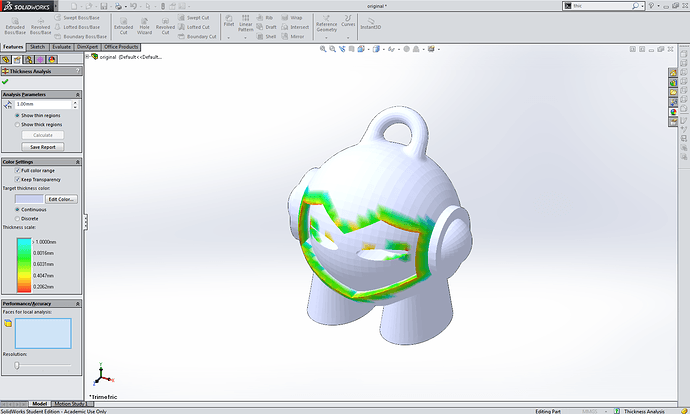
Wall thickness
The wall thickness, or the minimum wall size of your model, is another important parameter you need to take into account. Too thin walls might make your model non-printable or break after completion.
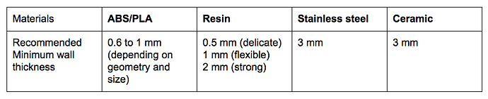
Luckily, the Thickness Analysis utility tool makes it ridiculously easy to to check the size of your walls in SOLIDWORKS. Use the table below for reference:
This values are indicative and can vary depending on the nozzle size of the printer in use.
Material related tips
- Fitting and material tolerance
FDM printers mostly print out of ABS and PLA plastics. When printed ABS cools down it shrinks of approximately 8% whereas PLA only shrinks about 2%. These values are indicative and can vary depending on the ABS/PLA being used. This is especially important to consider if you want to print an assembly with moving parts or multiple pieces that need to fit together for example.
SLA is the preferred rapid prototyping solution when extremely tight tolerances are required, as the cross sectional area of the laser can be made smaller than the extruder nozzle in the FDM method. It’s good to keep in mind though, that SLA is much slower than FDM.
Same goes for SLS, in terms of accuracy and printing time, with industry averages at around 0.1mm tolerances. Even though this method allows for far more complex geometries, it is only suitable for low volume production runs of small, precise parts.
- Resistance and saving on costs
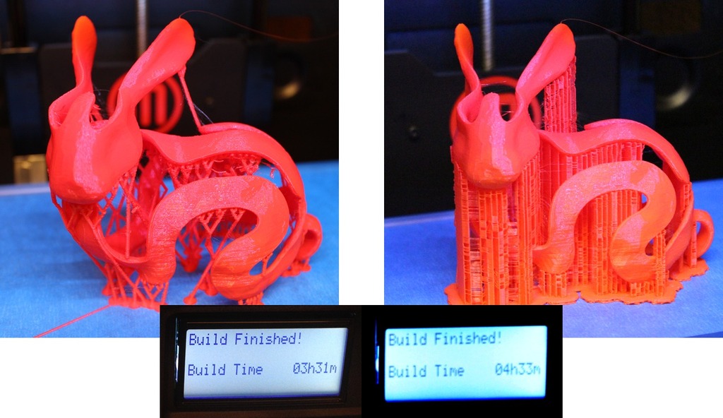
It’s always good to keep in mind the printing technique you intend to use for your design. For example, FDM and SLA printers require the generation of supports to be able to print overhanging parts. On top of impacting the amount of material used and printing time, support structures can leave marks after being removed and can induce a long post-processing cleaning.
Voronoi shaped Stanford bunny 3D printed with an optimal number of supports (left figure) (photo credit: Ryan Schmidt)
For SLA prints Use the Align feature to get your model under the best alignment and then generate only the minimum required amount of supports. (This step will be handled by the SLA printer proprietary slicer software).
- Printing large objects and/or assemblies
Every printer has a different bounding box size, which can impact how your model will be printed. The bounding box refers to the maximum X,Y,Z coordinates a printer can print in one piece.
If your model is larger than the size of the bounding box you can break it down in multiple parts using the Split tool. Then add snap hooks or mounting bosses so you’ll be able to assemble it back - check out this Fasten your Design tutorial for more details.
If you want to see how to create a bounding box to check if your design will fit the printer, make sure to have a look at this SOLIDWORKS tutorial.
If the model you’d like to get 3D printed is an assembly there’s two ways to go:
- Split it up in multiple parts, to be printed separately or on the same print bed.
- Print the whole assembly in one time is manageable too but be sure to take the tolerance between parts into account
2. Export for 3D printing
Here’s a step-by-step guide on how to export your SolidWorks design for 3D printing.
SolidWorks
- File > Save As…
- Set type to STL(*.stl)
- Click Options…
- Output as: check Binary
- Unit: > Millimeters or Inches
- Resolution > Fine
- OK
- Enter Filename
- Save
SolidWorks Student Kit
- File > Save As…
- Set type to eDrawings(*.eprt)
- Click Options…
- Check Allow export to STL for Parts & Assemblies
- OK
- Enter Filename
- Save
- Open part in eDrawings
- File > Save as… > select type STL Files (*.stl)
- Save
And that’s about it! Let me know if you have any questions or how this works out for you 
Happy printing!