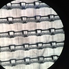
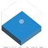
Hi! I’ve recently bought a form2 3d printer and I am trying to print a device which consists on an array of cubes (250x250x250 microns), as it can be seen in the image I have attached, there is an area in all the cubes that are diffuse, is it because it could need some support in that area? Did someone try a similar design or features of this sizes?
Thanks!!
1 Like
Form2 laser spot size is 140 microns so want it or not it’s going to mess up the math right there. Either make the cubes dimensions factor of 140 microns like 280x280x280 microns or higher, or get a small footprint jewelry printer with higher resolution for that size.
1 Like
cobnut
3
@shahramrobotics although the spot size is 140µm, the laser can focus on any point on the print bed, down to about a 10µm precision, it’s not a grid of 140µm square pixels like a DLP printer so it’s certainly possible to print embossed features like this at 250µm. Attached is a graph of Formlabs results of a test for resolution on the XY plane, as you can see, anything down to about 200µm is spot on, and 150 is darn close. 250µm should be a walk in the park and I regularly print details at and below this level.
@alexrp92 supports won’t help as the minimum touch point is 300µm - the support itself would be larger than the feature and very difficult (if not impossible) to remove cleanly. How was the model aligned on the bed? It looks like it was printed with the disk almost vertical, which side faced the wiper? Have you tried it at 90 degrees (so the “bars” are parallel to the bed)? I’d also try printing it a little flatter, say at 45 - 60 degrees.
Have you been in touch with Formlabs support? They’re usually very helpful.
Hi Jack,
I was talking about surface filling not positioning. You’re right, you can put your model anywhere with 10 microns resolution and have model dimension factor of 10 microns which is related to the resolution of the step motors for the reflectors. But for dimensional accuracy it doesn’t work that way, although the laser can be pointed in 10 microns resolution like a grid in XY plane, the laser spot size is way bigger than that. It’s like a paint brush in photoshop and you want to do a zigzag filling to paint a rectangle 250x250 but the brush size is 140x140, you CAN draw a rectangle of 250x250 by overlapping your zigzag paints in photoshop but the slicing software for surface filling won’t work that way, they don’t do laser overlapping in 3d space while slicing your model, that’s why even some fine details disappear from your model right away in the sliced model preview before printing. Even the results you attached supports my first statement  the accuracy of the print won’t go lower that 140 microns even though the laser positioning has 10 microns resolution. So to get more accurate prints off of your SLA printer it’s better to have models with dimension factor of laser spot size to make sure the XY plane surface filling method works 100% correctly.
1 Like
cobnut
5
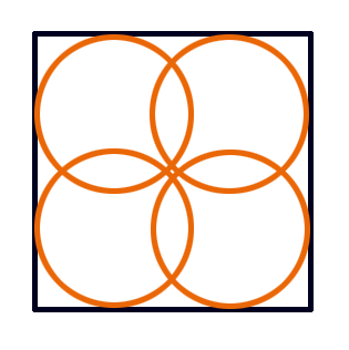
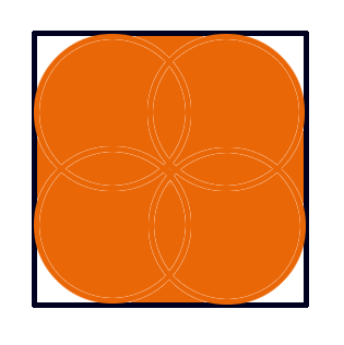
Hi @shahramrobotics I can totally understand the Photoshop analogy, however, that raises other questions (for me!) when looking at the image from @alexrp92. If we have a square at 250x250 and a spot that’s 140 in diameter, it seems to me that it should be impossible to get good corners for that square. See attached first pic. The spot could get no closer to the corners than shown, so the filled square should look something like the orange area of the second pic (assuming the “circle” is able to be positioned to 10 microns multiple times within the square). However, Alex’s image shows quite sharp corners on the left-hand side, they’re not pin-sharp, but they look a lot more “square” than fitting a 140 micron circle into a 250 micron square suggests should be possible.
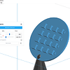
Not sure what slicing software you’re using, but Preform (for Formlabs) does not remove details at this level (see final image). This is a quick mock up of Alex’s model, the cubes are 250 microns, the support touch point 300 microns.
Not really arguing here - I’d certainly agree you can’t fit a circular peg perfectly into a square hole - I’m more just interested in the tech/processes! 
1 Like
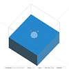
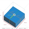
The important thing is that the laser intensity distribution is like a Gaussian kernel, it doesn’t have the same intensity in all areas, it’s stronger in the center and weaker on the edges. You can see in the attached photos the exact 250x250x250 microns cube sliced in preform. If you look at the first image you see two rectangles as the shells and one teeny tiny line in the middle as surface filling. As you increase the size of the cube (third image) the shells stay on the edges with the exact same outter offset and the rest of the model is filled by a zigzag pattern (shown as parallel light blue lines). So for the thickness of the shells you can see in the second image I came up with a rough estimation of 100 microns which makes sense, it’s like the laser spot was drawn on the blue line with ~50 microns area all around it to cure the resin. So I think in preform they considered the effective laser spot size a little less than the specs like around 100 microns. That’s why you get even better and sharper results than your calculations for 140 microns. I believe the diffusing problem is caused by a combination of uneven laser intensity distribution and the way Form2 detaches the model from the resin tank to move to the next layer. It pulls the model up while sliding the tank to the right, so the remaining resin on one side is pulled and removed but the other side is pushed to the side of the model, and specially for Alex project it quickly starts to collect the resin on one side because there is no way for the resin to go out. And of course the extra resin start to cure gradually on one side. I think he can fix that by just changing the orientation of its model.
Preform 3d representation is not really close to what the laser is actually getting from the gcode, it should be uglier, I like XYZware print preview much more, it’s more realistic. 
1 Like
cobnut
7
Thanks @shahramrobotics that makes sense. On the print tray release issue I did wonder whether the separation process had something to do with the shape of the cubes, hence my question in an earlier reply about which side faced the wiper.
I actually printed my model to see how it would come out, then discovered it was a pointless exercise as I have nothing in house that’s able to get a decent photo of it, or even magnify it enough to view with the naked eye! It’s hard to appreciate just how tiny these features are that we’re discussing until you hold it in your hands and realise that the whole disc is only about 2.5mm wide 
Do you think a DLP printer would be a better option for Alex? One that was able to use small enough square pixels?
If he gets a DLP with a projector that gives him the option to resize the image using the lens then he can make the image smaller for higher accuracy but he also needs a resin with lower viscosity to get much cleaner and sharper models.
1 Like