Hi Guys,
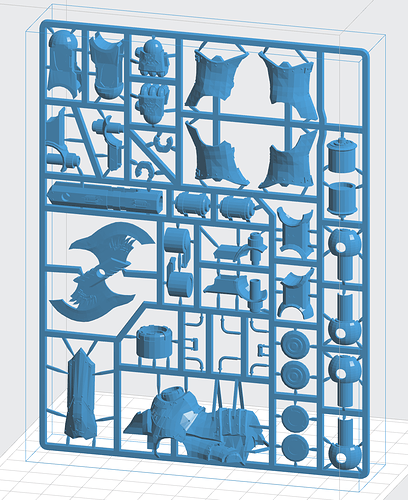
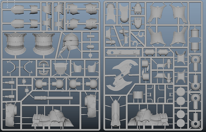
I’ve created a really complex model that needs to be printed but it’s not a single watertight mesh. Making it a single body will take a lot of time and putting it in zbrush and dynameshing it created a 2 bil poly mesh that is too complex for PreForm to handle.
Is it possible to just print it the way it is? Preform accepts the model and I can place it in the slicer and generate supports but I dont want to waste 50 dollars of resin and loads of time for nothing.
Thanks in advance
It will not print in its current form. You’d need to make a few changes… honestly, I’d break it apart. Complex mesh can be simplified… Martin
1 Like
Hey Alex Can you give us the form file and let us take a look at it for you. Or the file Business email Bobcat1250@yahoo.com Cheers Jake
Yeah, this won’t print as is. PreForm has about a 3 million vertex limit, and you’ll need to break it apart to allow for supports and good orientation. Also, looking at the level of detail, this really really doesn’t need to be that high poly. You could probably get away with 500k polygons, easily, and achieve the same level of detail.
1 Like
HI alex,
Why the injection molded look ? just curious !? Because of the nature of the preform sla method you wil need a lot support structure. i would also take it apart and print in a few go’s also it’s better to control failure if it happens of course. also with the model you supplied the orientation is maybe difficult for some detailed parts. So i would go with smaller print jobs!
Good luck
regards Marcel
Hi Alex,
I would recommend to break it appart.
Some layers will cure but will stay at the bottom of the tank as there is nothing to attach them to a previously cured layer / build platform
C
1 Like
Use the decimate tool in ZBrush to get the poly count back down.
1 Like
2B seems like excessively high resolution. Are you able to try decimating the model after assembly to reduce it to some sort of realistic level of 3D printable detail?
1 Like
Looking at the faceted surfaces, I can not imagine why this file needs so many vertices or triangles. It looks like the frame and the supports are the smoothest things in this build. It sure seems you should be able to decimate it to a much lower count. You could even split it into sections to decimated and then combine them if the whole thing is too big to process for triangle reduction.
1 Like
Hi Alex, is that for your own printer or for 3D hubs? If 3D hubs you’re much better getting it done on an HD SLS hub, as they could print it as-is no problem. If you’re trying to print it on a Form 1/2 then personally I wouldn’t even attempt to print it like that. I can’t speak for the Form 2, but our Form 1+ would probably have a near 100% failure rate on a print that big. If you can, cut it up into easily manageable sections then glue it back together (resin + a UV lamp makes a great way to join model parts). Remember you’ll still need Preform’s supports too, as others have mentioned your frame doesn’t have enough supports to support all the parts.
On the plus side Preform usually successfully cleans up multi mesh models and correctly solidifying them, also Netfabb’s free cloud service is generally good at cleaning up and solidifying models https://netfabb.azurewebsites.net/
@formwurx It doesn’t work as I can’t get the edges sharp enough. The tolerances on the model are very tight.
@nothinman Can you explain why it wont work?
@Richard_Beck The reason for the high poly count is that Dynamesh makes this whole thing a single watertight mesh. Now, if that mesh is even slightly off tolerance this thing doesn’t work. Dynamesh approximates the existing mesh so it comes out smoother than the original. And I need 0.05mm tolerances for this model at least.
@CollectorCNC Same answer as before but this time but decimation kills the edges.
@cyprien I see what you mean but that can be solved by applying supports to the parts that have the potential to break off.
@CopyPaste The whole idea is to make a prototype for an injection molded model kit. I’ve designed the entire thing from scratch and now Im looking for a way to print it in one piece so that the end product looks like it’s something you can buy in a shop. Thanks for the good luck  Seems like Ill need it.
@underline2 If you can tell me how to make this a single mesh with 500k polys and not lose detail Ill gladly do it.
@Keller89 Im sorry but Ive put about 3 months of work into this thing and Im not about to give it to other people for free.
Because it’s designed for injection moulding. You would either need supports here and there, or break the whole thing apart.
But to make your life easier, I’ll give you one killer argument. Tolerances on Form1/1+/2 are +/-0.25mm. Yes, that’s right.
That’s because these are cheap printers, with no f-theta lens.
It was intentionally designed to look like an injection mold. I’ve already mentioned that in one of the replies. And I know what the tolerances are. and they are fine. I’ve designed around them. Rule 1 of making stuff, know your tolerances.
It’s for a project that I cannot disclose at the moment sorry. It will not be posted on 3D hubs. However this was the first 3D printing community that popped up on a google search so I decided to try asking here.
I already got the idea from people that the print will fail but no one is specifying why. I can’t solve an unspecified problem because as far as I know this will even print perfectly when put up on it’s short side. The strains on it will be minimal. Im not planning on printing it flat. So I would love to know why it’s a problem
Yes I’ve just found an article that explains that I can intersect hulls but not planes which makes my setup just fine
Ok, I’d definitely say go with an SLS HD hub, the SLS process is self supporting and the entire thing can be printed in a single piece. An HD SLA hub with an industrial SLA printer might be able to do it too, but a consumer SLA printer like the Form 1 would really struggle.
I’m not following everything that’s being said here, but you’ve clearly said: " And I need 0.05mm tolerances for this model at least.".
You can’t printing it without supports, because some of these components are hanging in mid air (if you orient it any way you like, you will always have pieces hanging in the air). Think about how the printer prints it. First layer of each piece would need to be supported - it currently isn’t.
If you add support - that’s fine. But it will leave quite a few marks.
So yes, it can be printed, just like anything else. But not without the supports.
Does this answer your question?
The main issue is it you can’t have floating parts, as you move the layer slider up any layer that had nothing below it will be stuck to the bottom of the tank. Thus you’ll need lots of support poles coming from the bottom. You’ll probably need to angle the print so the support poles have space to get through, and I find when you have a lot of support poles on a very tall print there’s a good chance at least one will fail to fully print, which would then mean a hole in the model, which would ruin your print. A good way to visualise it is to use Preform’s auto-orient and auto-support function.
Sorry I’ve just realised you might not know how 3D hubs works. It’s actually a paid-for 3D printing service. It’s a bit like Uber in that individuals and companies with 3D printers register and perform paid 3D printing jobs. All jobs are confidential so the models etc are never made public.
There’s a whole range of people and printers offering their service, from 3D printing enthusiasts offering cheap prints on their FDM printer to companies with high quality industrial machines who use 3D hubs as a storefront.
Well, besides what can or cannot be done, I would face the problem from another perspective. If you want to make something that needs to work as master for a mould, I would print the parts independently, clean them off of the support and build the feeding line with some other material (e.g. plastic sticks, 3d printed, clay…) and glue the tips to the parts. This way, by assembling it, you would get the master cheaper and with much less stress than having it done in one piece.
SLS is indeed an option for such complex shapes, but the finish is not comparable with resin in general.
I also read in this post about +/-0.25mm tolerances… if the Form1 had that tolerance it wouldn’t have made it past the kickstarter. Such tolerance would mean that the laser spot would randomly position within a 0.25mm radius of the intended place, giving a finish probably even worse than FDM (i.e. a straight wall would be full of grooves, not smooth-ish, thing that is not true on my Form1+ at least). The 0.25mm can be regarded as resolution, or more correctly, minimum feature size on the xy plane. The f-Theta lens would definitely reduce this spot size, but at a huge cost on printing time. The difference between building a wall with bricks or with mosaic tiles. Without considering the costs of this optics, in particular for the short optical paths inside a desktop machine. To be honest I don’t recall having seen such lens either on industrial SLA printers, but I may be wrong… There are some tricks you can use to avoid it, taking advantage of small diameter beams and long focal lengths.
As long as the galvos work fine and don’t deviate (placing the bricks well aligned) I consider myself well happy, to be honest.
Well, it it +/-0.25mm due to the lack of f-theta lens. I have measured it, and so have others.
Note this doesn’t mean it would change +/-0.25mm at the same XY point. It won’t.
“Tolerance” here means the difference between the corners and the centre.
Here’s more info: https://docs.google.com/document/d/15F\_J7PCEi\_f8WhMbFRHXbmZs7yPihz7wigxNsn5TjJQ/edit
Optical path in Form1 is long enough for an f-theta lens. A single f-theta lens is approximately $400. I’d personally pay this extra, if Formlabs were to offer this as an option.
The purpose of f-theta lens is not to reduce the spot size, but to correct the distortion. This has no effect on the printing speed.
Without it, the spot becomes an ellipse in the off-centre regions.
1 Like