


CNC turning service
Source high-performing parts in more than 50 different metals and plastics via our network of advanced CNC turning experts. Tight tolerances available, down to ±.0008"
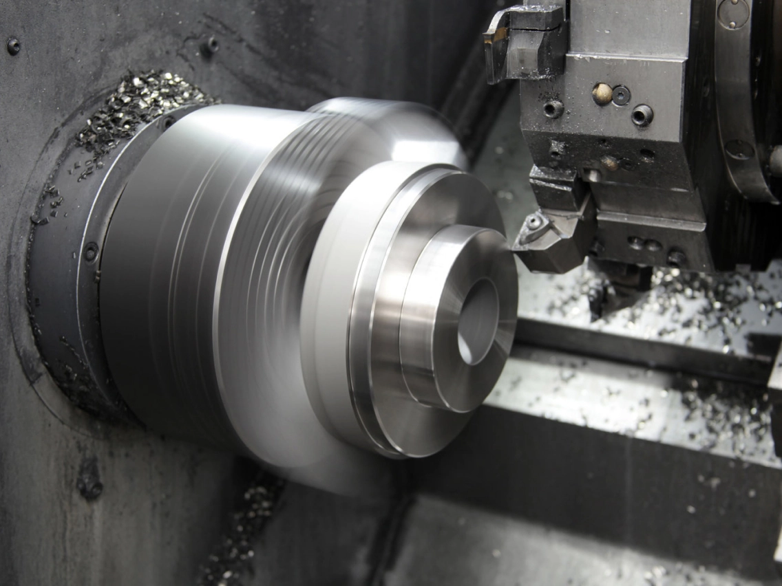
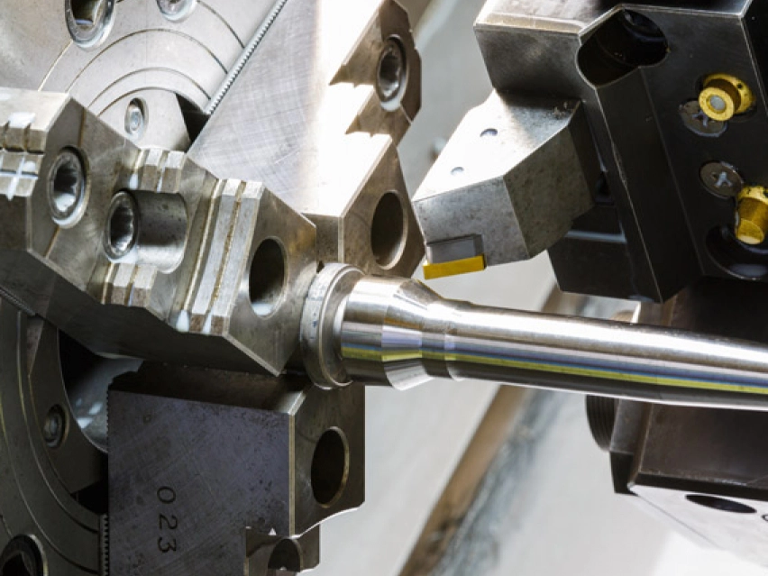
What is CNC turning?
CNC turning produces parts by mounting a blank on a rotating chuck and removing material using stationary cutting tools. This technology is ideal for manufacturing parts with symmetry along their center axis. Turned parts are typically produced faster (and at a lower cost) than milled parts.
Learn more about CNC milling and turning
Maximum part size for CNC turning
| Part size limitations | Metric units | Imperial units |
|---|---|---|
| Maximum part diameter | 431 mm | 17 in |
| Maximum part length | 990 mm | 39 in |
| Maximum swing over the carriage | 350 mm | 13.7 in |
| Maximum spindle through-hole | 40 mm | 1.5 in |
| Maximum speed: 1700RPM, Motor power: 640W |
Available materials for CNC turning
Industry-leading companies in aerospace, automotive, defense, machinery, medical technology, robotics, electronics, oil & gas, industrial automation and more that require high degrees of detail and complexity come to us for rapid prototypes and production parts.

A wide range of metals for CNC machining, with applications in multiple industries. Ideal for both one-off prototypes and end-use custom parts.
Browse CNC turning metal materials

A wide range of plastics for CNC machining, with applications in multiple industries. Ideal for both one-off prototypes and end-use custom parts.
Browse CNC turning plastic materials
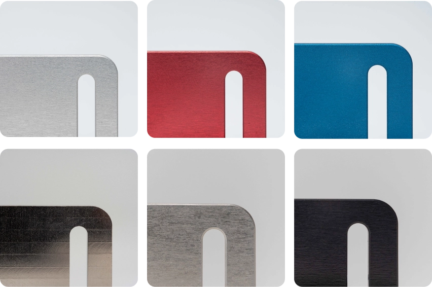
CNC turning surface finishes
Enhance part performance by selecting surface finishes that improve the roughness, hardness, chemical resistance and cosmetic features of the finished component.
Browse CNC turning surface finishes
CNC turning tolerances
We follow ISO 2768 standards for CNC machining.
| Limits for nominal size | Plastics (ISO 2768- m) | Metals (ISO 2768- f) |
|---|---|---|
| 0.5mm* to 3mm | ±0.1mm | ±0.05mm |
| Over 3mm to 6mm | ±0.1mm | ±0.05mm |
| Over 6mm to 30mm | ±0.2mm | ±0.1mm |
| Over 30mm to 120mm | ±0.3mm | ±0.15mm |
| Over 120mm to 400mm | ±0.5mm | ±0.2mm |
| Over 400mm to 1000mm | ±0.8mm | ±0.3mm |
| Over 1000mm to 2000mm | ±1.2mm | ±0.5mm |
| Over 2000mm to 4000mm | ±2mm | |
| *Please clearly indicate tolerances for nominal sizes below 0.5mm on your technical drawing. |
CNC turning design guidelines
Check the recommended and technically feasible values for the most common features of parts produced with precision CNC turning.
Learn more in our engineering guide to CNC machining
| Feature | Recommended size | Feasible size |
|---|---|---|
| Min. feature size | Ø 2.5 mm | Ø 0.50 mm |
| Internal edges | R 8 mm | R 0.25 mm |
| Minimum wall thickness | 0.8 mm (for metals) 1.5 mm (for plastics) | 0.5 mm (for metals) 1.0 mm (for plastics) |
| Holes | Diameter: standard drill bit sizes Depth: 4 x diameter |
Diameter: Ø 0.5 Depth: 10 x diameter |
| Threads | Size: M6 or larger Length: 3 x diameter | Size: M2 |
Why should you choose CNC turning?
We have high standards for CNC turning
We manufacture your custom parts according to strict manufacturing standards and ensure all parts and processes adhere to The Protolabs Network Standard.
-
Several surface finishes are available to improve the cosmetic quality of your parts after machining.
-
Every custom part gets checked on site by our manufacturing partners according to our guidelines.
-
Inspection reports and other types of quality documentation are available on request to assure the highest quality and compliance.
More resources for CNC turning
Learn more about how CNC turning works and how to design better parts for this machining process.