


Additive technologies compared
Metal 3D printing

Ready to get your parts printed?
Get an instant 3D printing quote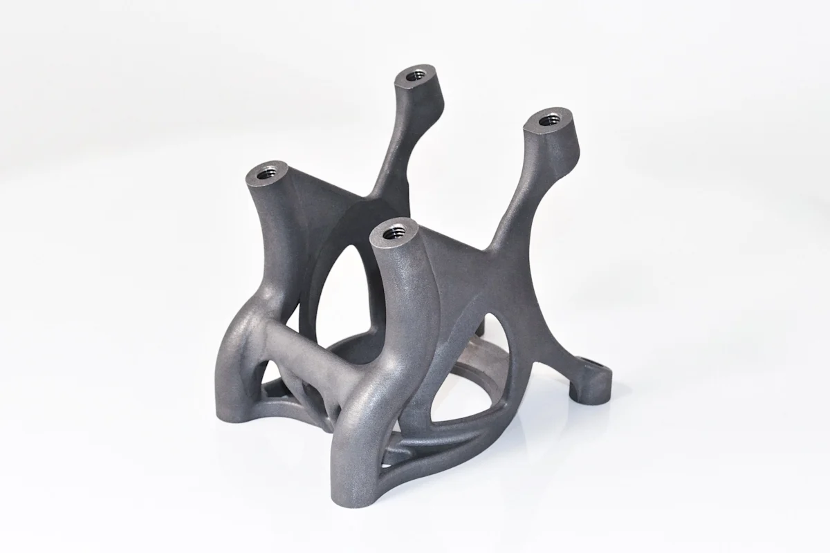
SHARE THIS ARTICLE
SHARE THIS ARTICLE
Metal 3D printing is currently on the rise. This guide will show you how to get the most out of metal additive manufacturing. Get a complete overview of today’s metal 3D printing landscape, master its unique benefits and limitations and learn when and how to use the three most popular metal 3D printing technologies: DMLS/SLM, binder jetting and metal extrusion. If you need metal 3D printed parts, check out Protolabs’ 3D printing metal service.
Part 1
The basics
How do metal 3D printers work? What are their key benefits and limitations? How is metal 3D printing used in the industry today?
In this section, we will answer these questions and we will learn more about the basic mechanics of each metal 3D printing process. Through a comparison with “traditional” manufacturing, you will you gain a deeper understanding of the current state of metal 3D printing and its great potential.
How do metal 3D printers work?
Similar to all other 3D printing processes, metal 3D printers build parts by adding material a layer at a time based on a digital 3D design - hence the alternative term additive manufacturing.
This way, parts can be built with geometries that are impossible to manufacture with “traditional” subtractive (CNC machining) or formative (metal casting) technologies, and without the need for specialized tooling (for example, a mold).
From here, the specific steps each metal 3D printer follows to manufacture a part vary greatly by technology:
Powder bed fusion
A high-power laser (in DMLS/SLM) or an electron beam (in EBM) is used to selectively bond metal powder particles together, layer-by-layer forming the metal part.
Manufacturers: EOS, 3D Systems, Renishaw, SLM Solutions, Concept Laser, Arcam
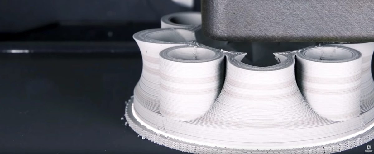
Binder jetting
Metal powder particles are bound together with an adhesive layer-by-layer, forming a “green” part that needs to be thermally post-processed (sintered) to remove the binder and create a fully-metal part.
Manufacturers: Desktop Metal, ExOne, Digital Metal, HP
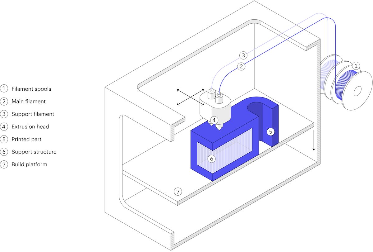
Metal material extrusion
A filament or rod consisting of polymer and heavily loaded with metal powder is extruded through a nozzle (like in FDM) to form the “green” part that is post-processed (debinded and sintered) to create a fully-metal part.
Manufacturers: Desktop Metal, Markforged
Ultrasonic additive manufacturing
Metal foils are bonded layer-by-layer using ultrasonic welding and then formed to the design shape using CNC machining.
Manufacturers: Fabrisonic
Other processes
Other metal 3D printing systems have been developed over the years based on established plastic 3D printing technologies (such as material jetting or SLA).
3D printing has also been used to create tooling for “traditional” metal manufacturing, such as sand casting or investment casting.
Today, the most commonly used metal 3D printing processes are Direct Metal Laser Sintering (DMLS) / Selective Laser Melting (SLM), followed by binder jetting and metal extrusion.
If you want to dive deeper into the basic mechanics, particular benefits and limitation, and capabilities of each of these technologies, jump directly to the next part of this guide.
For the rest of this section, we will focus on the general aspects of metal 3D printing that apply to all processes. We will also explore how they compare with “traditional” manufacturing processes. This way you will gain a broader understanding of how to get the most out of this unique manufacturing technology. But first, a short history lesson…
A brief history of metal 3D Printing
- In the late ’80s, Dr. Carl Deckard of the University of Texas developed the first laser sintering 3D printer of plastics. This invention paved the way for metal 3D printing.
- The first patent of laser melting of metals was filed in 1995 by the Fraunhofer Institute in Germany. Companies like EOS and many Universities lead the development of this process.
- In 1991, Dr. Ely Sachs of MIT introduced a 3D printing process that is today better known as binder jetting. Binder Jetting of metal was then licensed to ExOne in 1995.
- Metal 3D printing saw slow but steady growth in the ’00s. This changed after 2012 when the original patents started expiring and large investments were made by companies like GE, HP and DM.
- Today, the Wohler’s report estimates metal 3D printing to be a $720 million market and growing rapidly. In 2017 alone, the sales of metal 3D printers increased by 80%.

Benefits & limitations of metal 3D printing
It is important to understand that metal 3D printing is a powerful tool that comes with many unique benefits. Yet, its current limitations do not always make it the best option when it comes to manufacturing metal parts.
These are the most important advantages and disadvantages of metal 3D printing. Use them to understand where metal 3D printing stands today and where it is headed in the near future.
Benefits of metal 3D printing
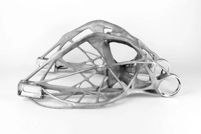
The greatest advantage of metal 3D printing compared to “traditional” manufacturing is its exceptional design flexibility. Since no specific tooling is needed (for example, a mold or a cutting tool), geometries that are impossible to manufacture through other processes are easily 3D printable.
More importantly, increasing the geometric complexity of a part has almost no effect on its manufacturing cost. This means that organic, topology optimized structures can be used with metal 3D printing, to greatly improve the performance of the produced parts.
The great design flexibility of metal 3D printing goes hand in hand with the creation of lightweight structures. In fact, following best design practices for metal 3D printing always gives a lightweight solution.
Typically, advanced CAD techniques, such as topology optimization and generative design, are usually used for this purpose.
This result in parts with both less weight (typically, by 25% to 50%) and higher stiffness. This is key for high-end applications in industries like the aviation and aerospace.
Since tool access is not an issue in metal 3D printing, parts with internal structures can be manufactured.
For example, internal channels for conformal cooling are a great way to increase the performance of a part. Injection molding cores with conformal cooling - manufactured through DMLS/SLM - can reduce injection cycles by up to 70%.
Another example of increased part functionality comes from metal extrusion. Using this process, custom jigs and fixtures with complex geometries can be created when needed, increasing the efficiency of operations of other industrial processes on the production floor.
Another great strength of metal 3D printing is its ability to merge an assembly into a single.
This eliminates the need for fasteners and results in parts that can serve multiple functions at once. Also, labor costs and lead times are minimized and maintenance and service requirements are reduced.
As an added benefit, reducing the total part count is another method to create lightweight structures.
Even when a part with complex geometry is manufacturable using “traditional” methods, it can take 20 or more production steps to do so.
In these cases, metal 3D printing should be considered as a valid manufacturing option. Using binder jetting, for example, the total number of steps can be reduced to five or less (including post-processing and finishing). This way the complexity of the manufacturing supply chain is greatly reduced.
Contrary to 3D printing of plastics, parts manufactured with DMLS/SLM or binder jetting show an isotropic mechanical behavior. Also, their material strength is comparable to the wrought metal (and in some cases even better). For this reason, metal 3D printed parts have found applications in the most demanding industries, like aerospace.
Note, though, that 3D printing parts generally have lower fatigue strength. This is due to their surface roughness and their internal porosity (typically, DMSL/SLM parts have < 0.2% porosity and binder jetting parts < 2%).
Limitations of metal 3D printing
Compared to traditional manufacturing methods, the cost of metal 3D printing today is considerable. On average, a typical DMLS/SLM part will cost you approximately $5,000 to $10,000 to 3D print and finish. So, it is important to keep in mind that the use of metal 3D printing makes economic sense only if it is connected with considerable improvement in performance.
There is a demand for affordable metal 3D printing solutions though. The new benchtop metal extrusion systems and production binder jetting systems could fill this gap in the near future.
Another limitation of metal 3D printing is that it cannot compete yet with traditional manufacturing when it comes to larger volumes.
The lack of custom tooling means that start-up costs are low, but also that the total manufacturing costs are not significantly affected by the volume of production. In other words, the unit price is almost unchanged at higher quantities and economies of scale cannot kick in.
Yet, the industry is working towards metal 3D printing systems that can streamline production. For example, DMLS/SLM machines with multiple lasers and Binder Jetting systems capable of continuous production are currently entering the market.
Designing parts for metal 3D printing follows a different set of rules than “traditional” manufacturing. This often means that existing designs have to be re-designed.
Moreover, the tools provided by older CAD software may not be enough to take full advantage of the benefits of metal 3D printing. For an extensive introduction to the main design consideration, advanced CAD tools and design rules for metal 3D printing, jump to the last section of this guide.
Almost every metal 3D printed part will need some post-processing before it is ready to use. This adds to the overall cost and delivery time.
Independent of the selected technology, combinations of thermal treatments, machining, polishing, and other finishing methods are almost always required to produce the final part. We will see more details on the necessary post-processing steps for each technology in later sections.
Applications of metal 3D printing
Here we collected examples of key industrial applications of metal 3D printing. They illustrate some of the main benefits and limitations of the technology. Use them to better understand why engineers chose metal 3D printing for their particular application.
Space
Creating lightweight structures is of paramount importance for the space industry. The current cost of launching a kilogram of payload into space is approximately $10,000 to $20,000. So, metal 3D printing of topology optimized parts has great potential here.
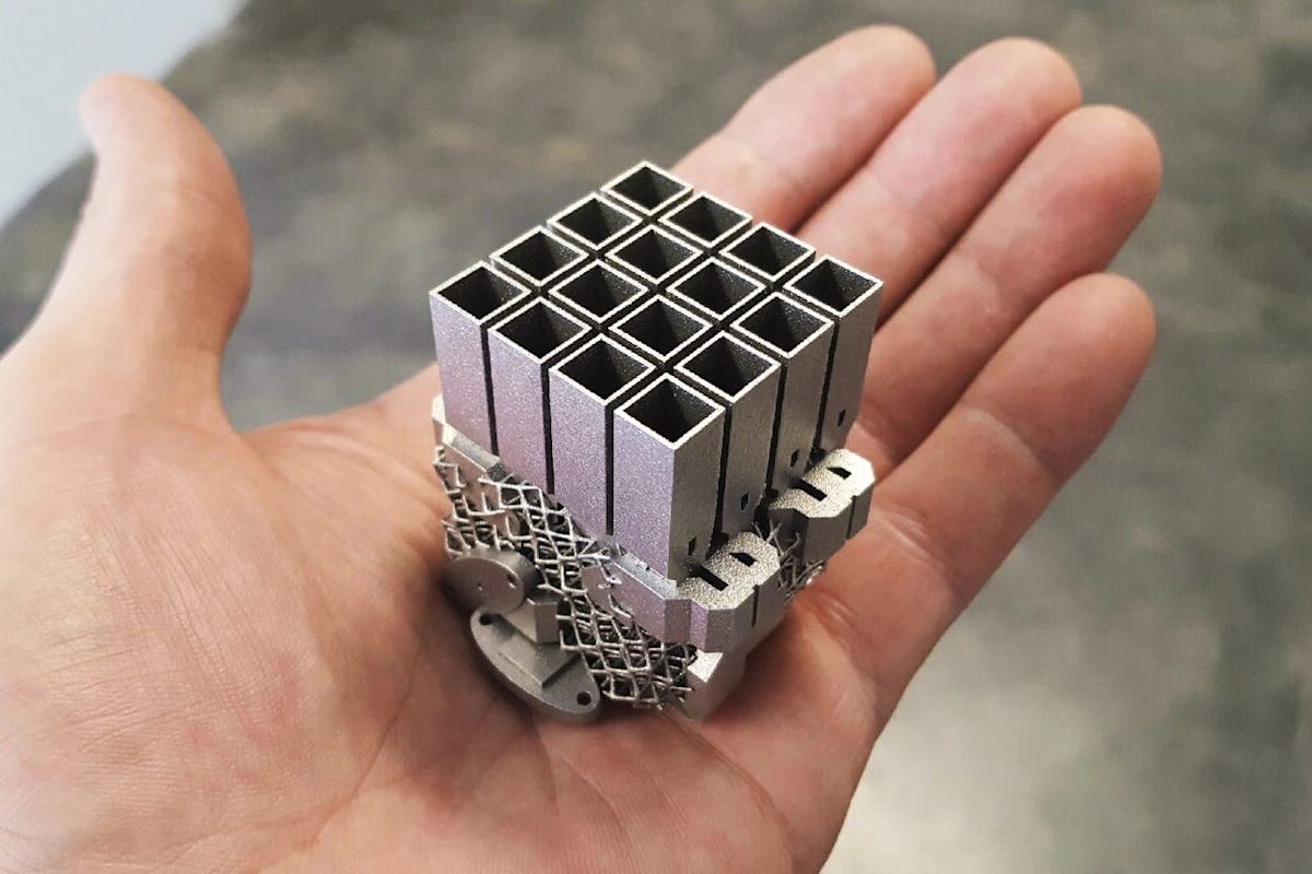
Optisys, for example, is a provider of micro-antenna products. They used DMLS/SLM to reduce the number of discrete pieces of their tracking antenna arrays from 100 to only 1. With this simplification, Optisys managed to reduce the lead time from eleven months to two, while achieving a 95% weight reduction.
Healthcare
The ability to create organic structures, personalized to the anatomy of every individual, makes metal 3D printing a very appealing solution for the medical industry. Today, medical implants from biocompatible materials (such as titanium) are one of the major uses of metal 3D printing.
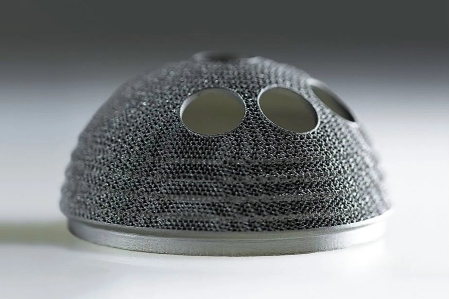
Back in 2007, Dr. Guido Grappiolo was the first surgeon to implant a 3D printed hip cup implant. With the help of LimaCorporate and Arcam, he designed the Delta-TT Cup, a titanium implant with a lattice structure that accelerates patient rehabilitation and bone growth. A decade later, more than 100,000 of these hip cups have been implanted successfully to patients.
Automotive
The adoption of metal 3D printing as a manufacturing option for end parts in the automotive industry is increasing rapidly. For the time being, high-performance and racing are the main applications of metal 3D printing.
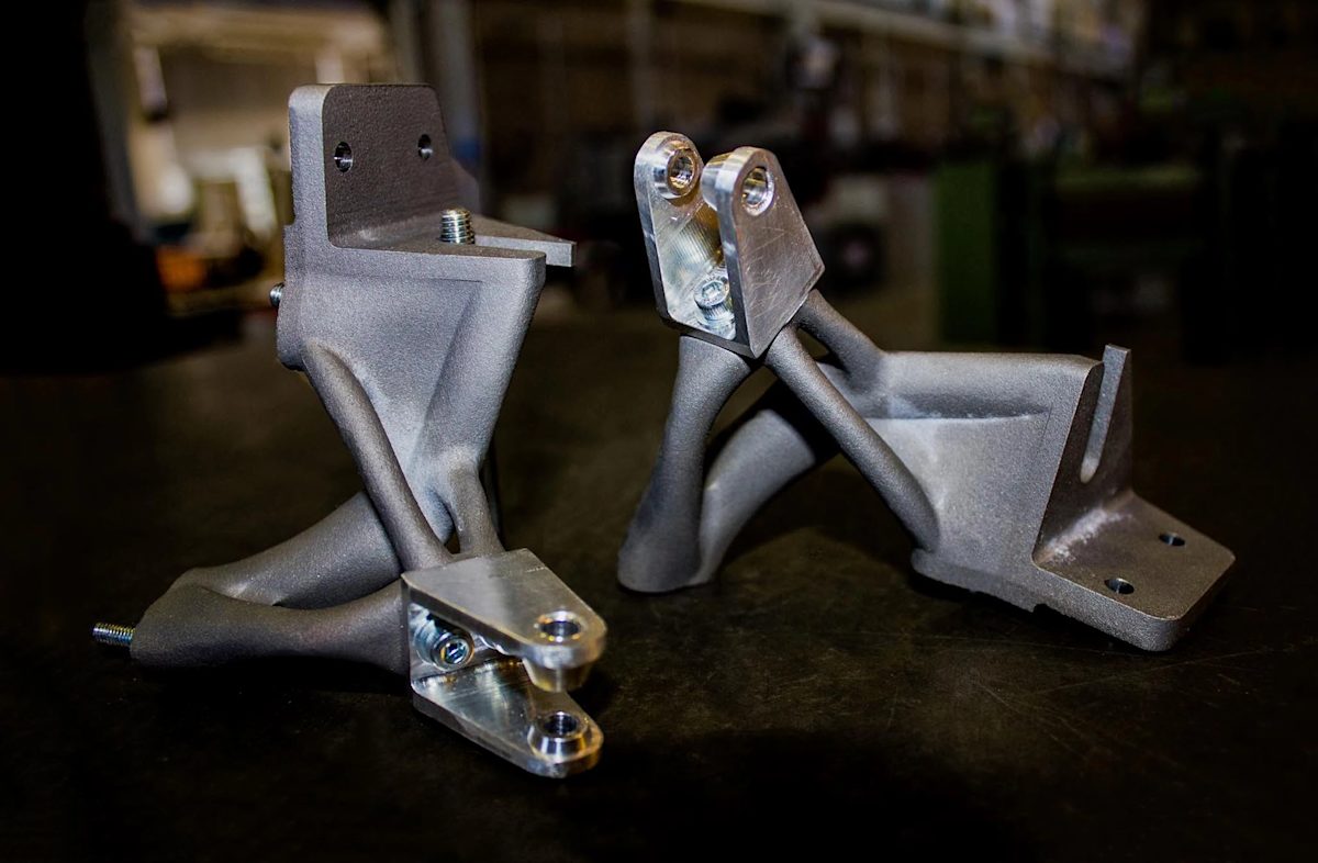
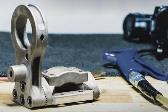
The TU Delft Formula Student team, one of the most successful teams in the history of the sport, used DMLS to manufacture their topology optimized bracket for their formula car. This bracket is the main connection point between the wheel and the chassis and it is designed to withstand forces up to 400 kg. The re-designed titanium bracket has half the weight and twice the strength of an equivalent part machined out of steel.
Industrial Tooling
Metal 3D printing is used today to create industrial tools with added functionality. These advanced tools can greatly increase the productivity of other proceses.
For example, metal molds with internal conformal cooling channels can be manufactured using DMLS/SLM 3D pritning. These cooling channels can be printed to any shape and closer to the part than subtractive methods can accomplish. A printed metal mold can cost about $10,000, which is considerable compared to the $4,000 that the same mold would cost if it was CNC machined. The increased cost brings significant performance improvements. Users reported injection cycles that are shorter by 60% to 70% with almost no scrap.
Product Development
The main applications of Metal Extrusion today is the manufacture of metal prototypes. When compared to other in-house solutions, the time savings offered by Metal Extrusion can greatly reduce the time-to-market of new engineering products.
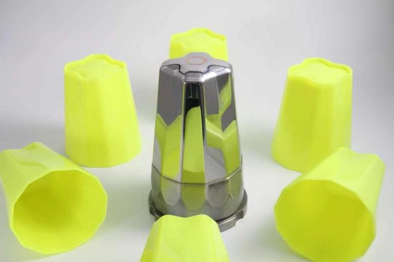
Lumenium is a start-up that develops innovative internal combustion engines. They were seeking a faster and more cost-effective approach to prototyping their engine parts. Traditionally, their development cycle is approximately 3.5 years. By incorporating Metal Extrusion in their workflow, they estimated that they reduced their development time by 25% to 2 years and 9 months.
Materials for metal 3D printing
The number of metal material available for metal 3D printing is growing rapidly. Engineers can today select from alloys including:
- Stainless steels
- Tool steels
- Titanium alloys
- Aluminum alloys
- Nickel-based superalloys
- Cobalt-chrome alloys
- Copper-based alloys
- Precious metals (gold, silver, platinum…)
- Exotic metals (palladium, tantalum…)
The cost of metal 3D printing
The cost of a metal 3D printer varies greatly between technologies. The selling price of a DMLS/SLM printer averages at $550,000 and can reach $2 million USD. Metal binder jetting systems cost approximately $400,000. A metal extrusion printer will cost you around $140,000 including the post-processing units.
The manufacturing cost of a typical DMLS/SLM part is approximately $5,000-$10,000 (including finishing). For binder jetting and metal extrusion, the cost per parts can be up to 5-10 times lower than that of DMLS/SLM parts. At the time of writing though, it is still early to assess the full operational cost of these systems.
The table below is a break down of the average costs of different manufacturing steps for DMLS/SLM. Notice that the material cost, as well as the cost of post-processing, contribute considerably to the overall cost.
| Production step | Operation | Cost |
|---|---|---|
| Manufacturing | Material cost | $200 - $500 per kilogram |
| DMLS/SLM cost | $2,000 - $4,000 per build † | |
| Post-processing | Stress relief | $500 - $600 per build † |
| Part/supports removal | $100 - $200 per part | |
| Heat treatment / HIP | $500 - $2,000 per build † | |
| CNC machining | $500 - $2,000 per part | |
| Surface treatments | $200 - $500 per part |
† Typically, six to twelve parts can fit on the same build plate.
The speed of metal 3D printing
Independent of the process, a metal 3D printed part requires at least 48 hours and an average of 5 days to manufacture and finish.
About 50% of the total production time is allocated to printing. This, of course, depends on the volume of the part and the need for support structures. For reference, the current production rate of modern metal 3D printing systems varies between 10-40 cm³/h.
The remaining production time is related to post-processing and finishing requirements. Thermal treatments contribute significantly to the total production time: a typical thermal cycle lasts 10 to 12 hours. Mechanical surface finishes can also be a time-consuming step as they need input from an expert (5-axis CNC machining) or manual labor (hand polishing).
Metal 3D printing vs traditional manufacturing
Always begin with a Cost vs Performance analysis, when you are choosing between a metal 3D printing and a subtractive (CNC machining) or formative (metal casting) technology.
Generally speaking, the manufacturing cost is mainly connected to the production volume, while the performance of a part depends greatly on its geometry.
The key strength of metal 3D printing is its ability to create parts with complex & optimized geometries. This means that it is ideal for manufacturing high-performance parts. On the other hand, it does not scale as well as CNC machining or metal casting at higher volumes.

As a rule of thumb:
The high cost of metal 3D printing can be only financially justified if it is connected to a significant increase in performance or operational efficiency.
Of course, each metal 3D printing process meets different industrial requirements. Use the tips below as general guidelines to understand which process is the most suitable for you:
- DMLS/SLM is the best solution for parts with high geometric complexity (organic, topology optimized structures) that require excellent material properties for increasing the efficiency of the most demanding applications.
- Binder jetting is the best solution for low-to-medium batch production that cannot justify the large economic investment of a formative method and for parts with geometries that cannot be efficiently manufactured with a subtractive method.
- Metal extrusion is the best solution for metal prototypes and one-off parts with geometries that would otherwise require a 5-axis CNC machine to manufacture.
The table below is a Volume vs Part Complexity matrix, showing the areas that each manufacturing process (additive, subtractive or formative) performs at its best. Use it as a quick reference:
| Quantity | Low complexity | Header | Header |
|---|---|---|---|
| < 10 parts | CNC machining | Metal extrusion CNC machining |
DMLS/SLM |
| < 100 parts | CNC machining | Binder jetting CNC machining |
Binder jetting DMLS/SLM |
| < 1,000 parts | CNC machining Metal casting |
Binder jetting CNC machining |
Binder jetting |
| 1,000+ parts | Sheet metal Metal casting |
Metal casting | - |
Part 2
DMLS & SLM
Direct metal laser sintering (DMLS) and Selective Laser Melting (SLM) are the most used metal 3D printing processes today. They are particularly suitable for high-end applications as they offer great design freedom & advanced material properties.
In the section, we will dive deeper into the manufacturing process, technical characteristics and benefits and limitations of these two, very similar processes.
What is DMLS/SLM 3D printing?
DMLS (Direct Metal Laser Sintering) or SLM (Selective Laser Melting) are two powder bed fusion metal 3D printing technologies. The practical difference between SLM and DMLS are very slim. For design purposes, the two technologies can be treated as the same.
They both use a high power laser to bond metal powder particles together to form a part layer-by-layer. SLM achieves a full melt, while DMLS causes the metal particles to fuse together on a molecular level due to the very high temperatures. Most metal alloys are compatible with the DMLS process, while only certain (pure) metal materials can be used in SLM.
How does DMLS/SLM work?
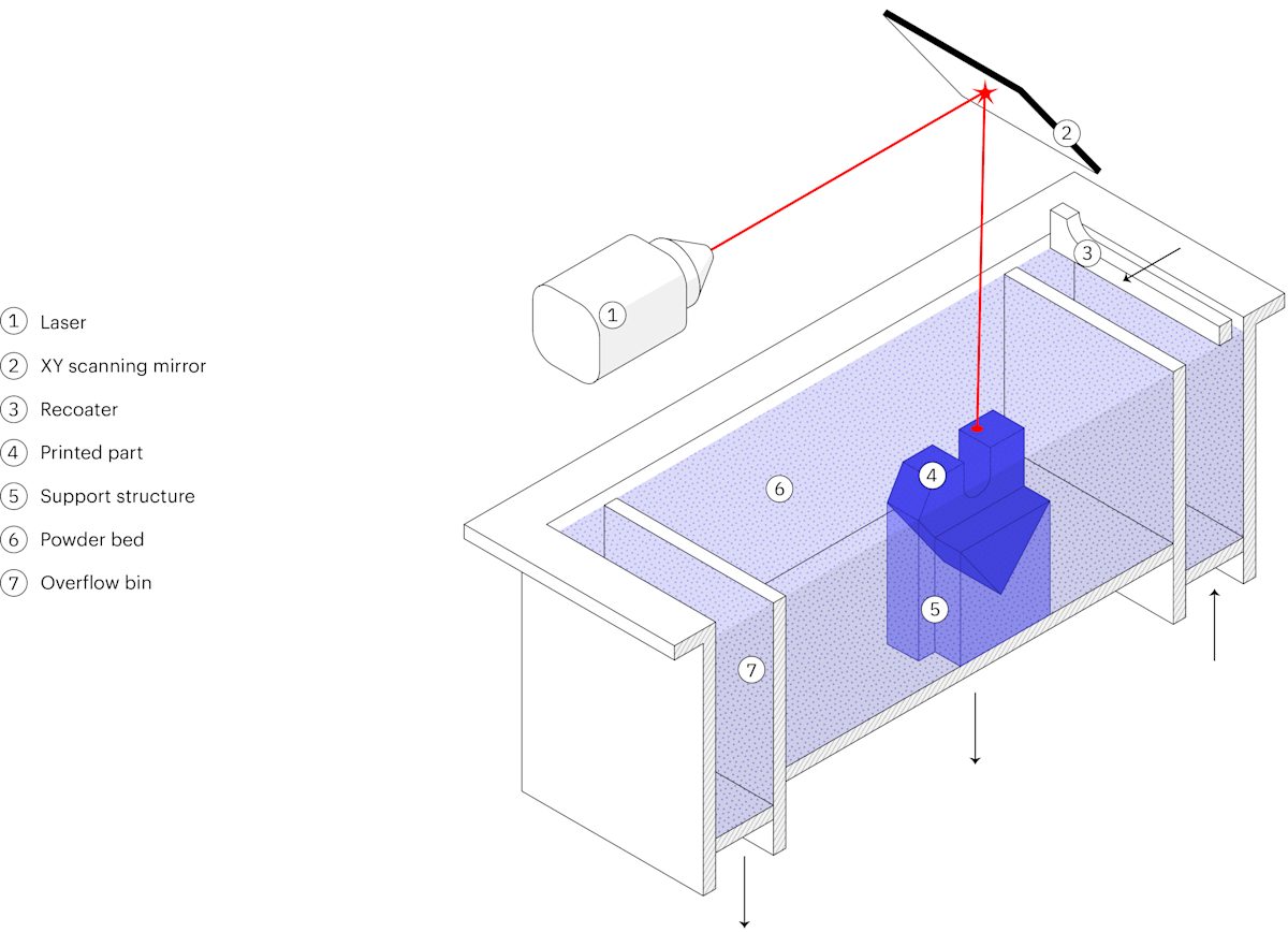
Here are the basic steps of the DMLS/SLM 3D printing process:
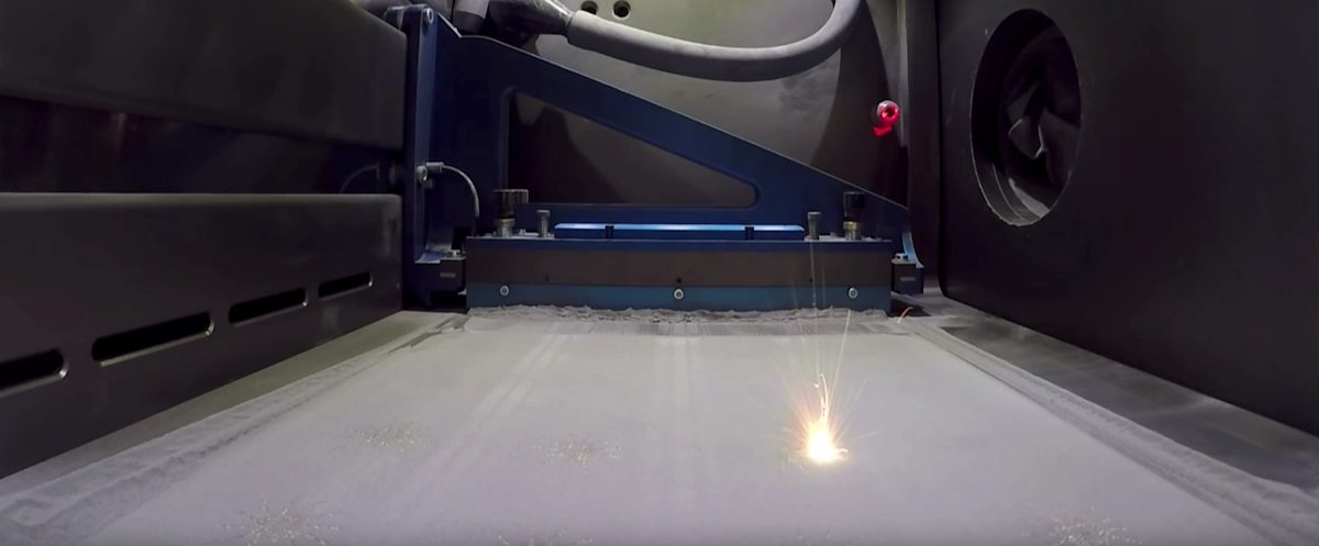
- The build chamber is first filled with inert gas and then heated to the optimal print temperature.
- A thin layer of metal powder (typically 50 μm) is spread over the build platform.
- The laser scans the cross section of the part, selectively bonding the metal particles.
- When entire area is scanned, the build platform moves down a layer and the process repeats until the whole build is complete.
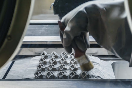
- After printing, the build first needs to cool down and then the loose powder is extracted.
The 3D printing step is only the beginning of the DMLS/SLM manufacturing process. After the print is complete, several (compolsory or optional) post-processing steps are required before the parts are ready to use. Compulsory post-processing steps include:
- Stress relief: Due to the very high processing temperatures during printing, internal stresses develop. These need to be relieved through a thermal cycle before any other operation.
- Removal of the parts: In DMLS/SLM the parts are essentially welded onto the build platform. A band saw or EDM wire cutting is used here.
- Removal of the support: Support in DMLS/SLM is always required to mitigate the warping and distortion that occurs during printing. Support is removed manually or CNC machined.
To meet engineering specifications, additional post-processing steps are often required. These may include:
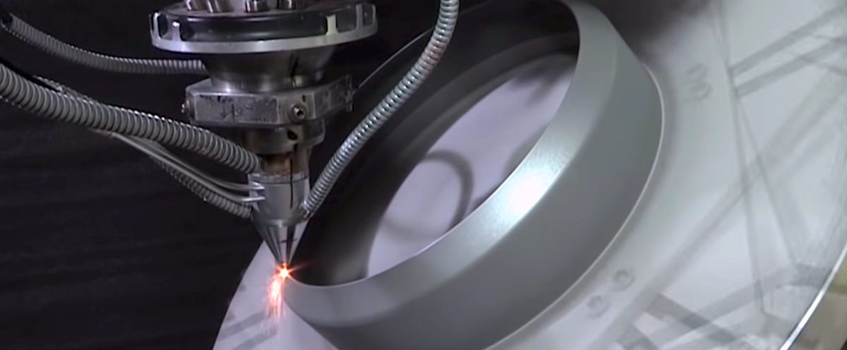
- CNC machining: When tighter tolerances than the standard ± 0.1 mm are required, machining is employed as a finishing step. Only minimal material is removed this way.
- Heat treatments: To improve the material properties of the part, heat treatments or Hot Isostatic Pressing (HIP) can be used.
- Smoothing/Polishing: Certain application require a smoother surface than the standard RA 10 μm of as-printed DMLS/SLM. CNC machining and manual, vibro or chemical polishing are all available solutions.
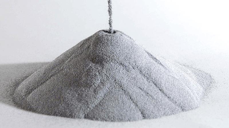
Metal powders for 3D printing
The raw material used in DMSL/SLM and many other 3D printing processes comes in a powder.
The characteristics of the metal powders are very important for the end results. To ensure good flow and close packing, metal particles need to have a spherical shape and a size between 15 and 45 microns. To achieve these tight requirements, methods such as gas or plasma atomization are commonly used.
The high cost of producing these metal powders is a key contributor to the overall cost of metal 3D printing.
Benefits and limitations of DMLS/SLM
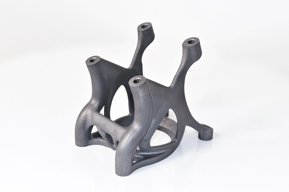
The main strength of DMLS/SLM is its ability to create highly optimized, organic structures from high-performance metal alloys.
Parts manufactured with DMLS/SLM can have a complex, organic shape that is optimized to minimize their weight while maximizing their stiffness. Or they can have internal geometries that cannot be produced with any other method.
The material properties of DMLS/SLM parts are excellent. Parts with almost no internal porosity are manufactured from a wide range of metal alloys, from aluminum and steel to high-strength superalloys.
We saw in a previous section though that the costs connected with DMLS/SLM are high. For this reason, it is only economically viable to use this processes for optimized parts for high-value engineering applications.
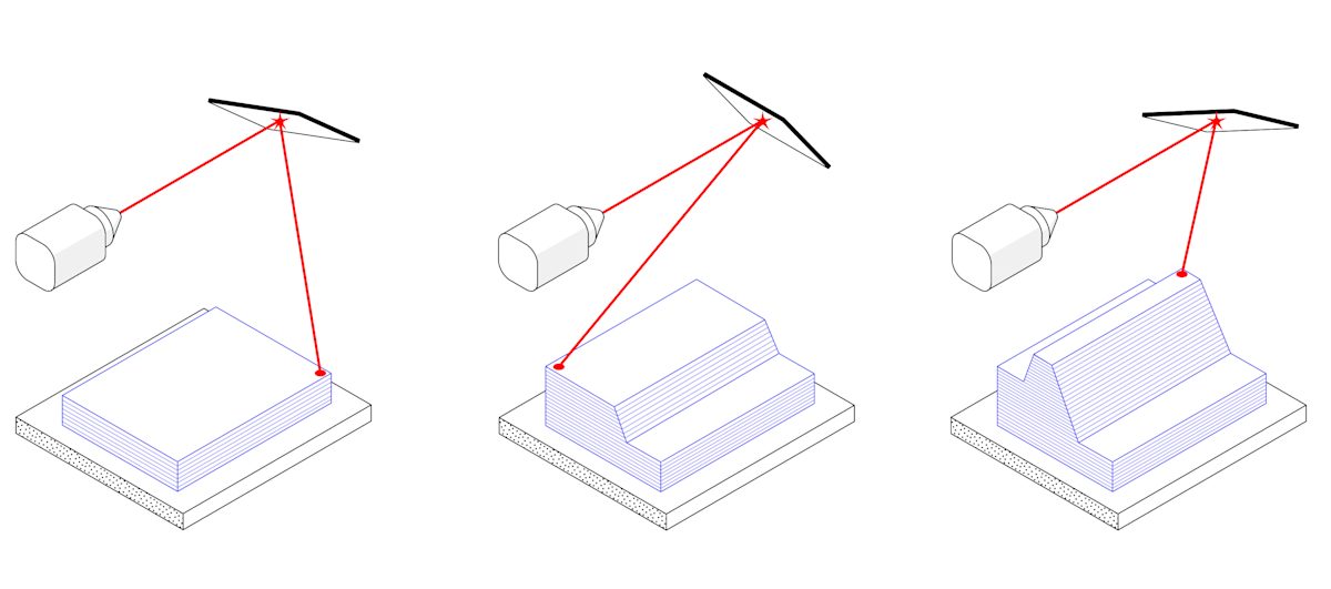
From a technical perspective, the main limitation of DMLS and SLM is their need for extensive support structures. These are needed to avoid warping and to anchor the part to the build platform. Also, out of the printer, the surface roughness of the produced parts is relatively high for most engineering applications, so post-processing is necessary.
Technical characteristics of SLM & DMLS
The table below summarizes the basic technical capabilities of a typical DMLS/SLM metal 3D printer today. For additional design guidelines, jump to the design rules.
| Property | DMLS/SLM |
|---|---|
| Material selection | Large range of materials currently available Aluminum alloys, titanium, stainless steel, tool steel, cobalt-chrome alloys, nickel superalloys, precious metals etc. |
| Dimensional accuracy | ± 0.1 mm |
| Typical build size | 250 x 150 x 150 mm (up to up to 500 x 280 x 360 mm) |
| Common layer thickness | 20 – 50 μm |
| Typical surface roughness | RA 8 - 10 μm |
| Support | Always required |
| Internal porosity | Less than 0.2 - 0.5% |
| Cost per part | $$$$$ |
Part 3
Metal binder jetting
Metal binder jetting is rapidly increasing in popularity. Its unique characteristics make it especially suitable for small-to-medium production runs.
In this section, we dive deeper into the steps followed in binder jetting and the basic characteristics of the produced metal parts.
What is metal binder jetting?
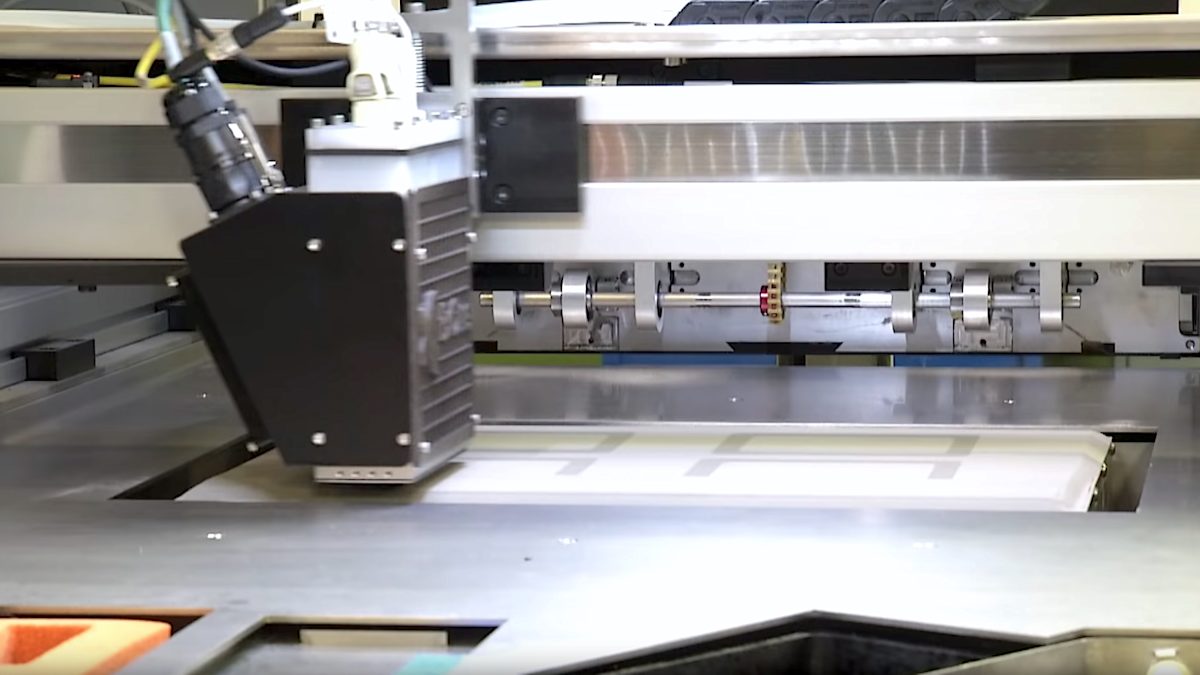
Binder jetting builds parts by depositing a binding agent onto a thin layer of powder through inkjet nozzles. It was originally used to create full-color prototypes and models out of sandstone. A variation of the process is currently raising in popularity due to its batch production capabilities.
The printing step in metal binder jetting printing takes place at room temperature. This means that thermal effects (like warping and internal stresses) are not an issue, like in DMLS/SLM, and supports are not required. An extra post-processing step is necessary to create a fully metal part.
How does Metal Binder Jetting work?
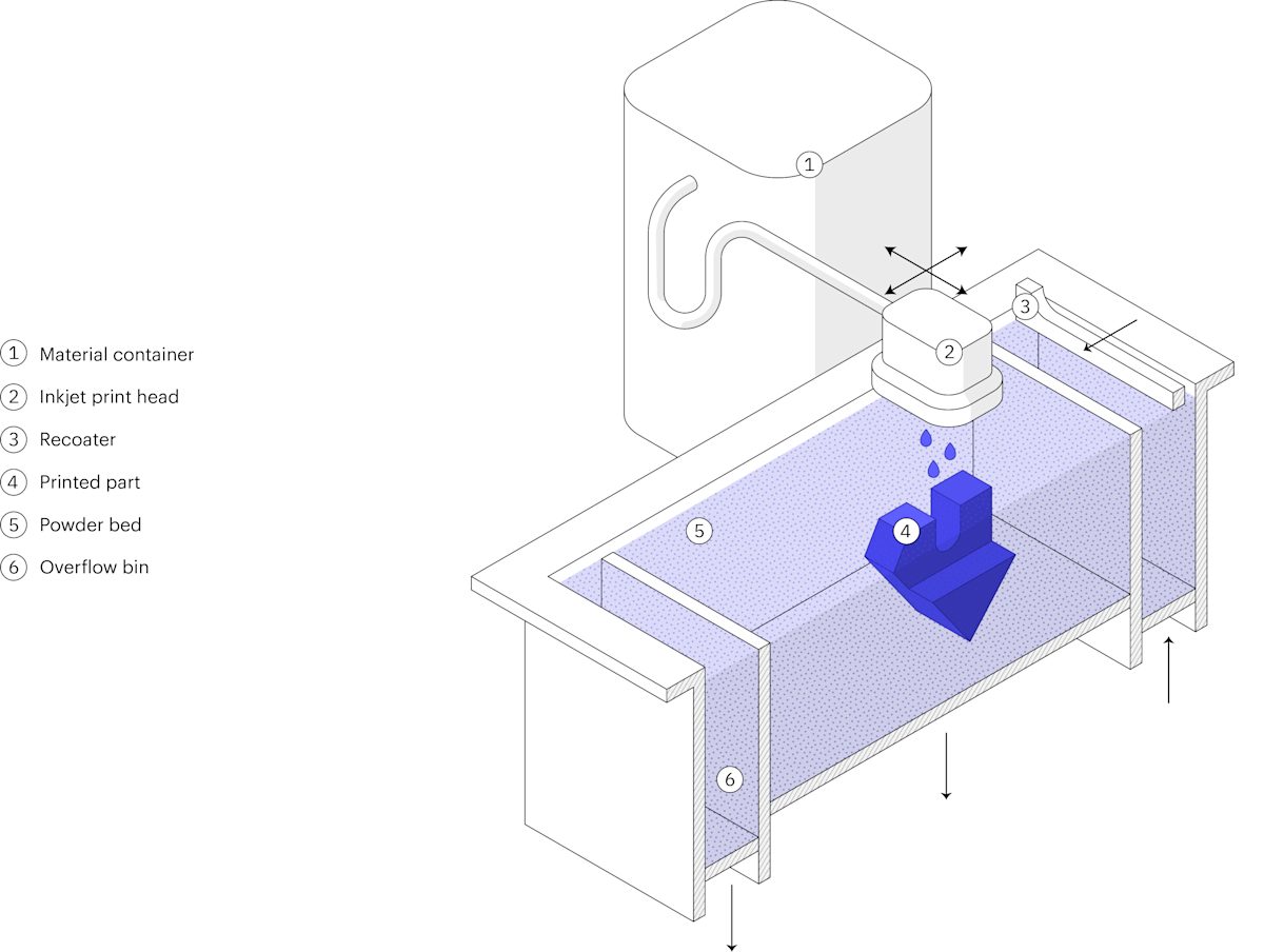
Metal Binder Jetting is a two-stage process. It involves a printing step and an essential post-processing step. Here’s how the printing process works:
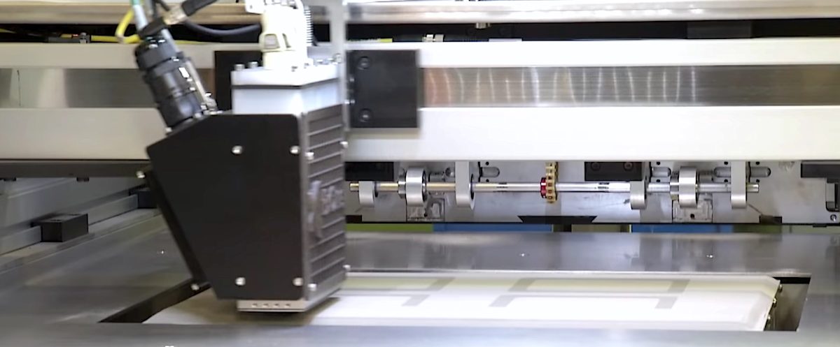
- A thin layer of metal powder (typically 50 μm) is spread over the build platform.
- A carriage with inkjet nozzles passes over the bed, selectively depositing droplets of a binding agent (polymer and wax), bonding the metal powder particles.
- When a layer is complete, the build platform moves down and the process repeats until the whole build is complete.
The result of the printing process is a part in the so-called “green” state. A post-processing step is required to remove the binding agent and create fully metal parts.
There are two variations for this post-processing step:
- Infiltration: The “green” part is first washed off from the binding agent to create a “brown” part with significant internal porosity (~70%). The “brown” part is then heated in an industrial oven in the presence of a low-melting-point metal (typically, bronze). The internal voids are filled, resulting in a bi-metallic part.
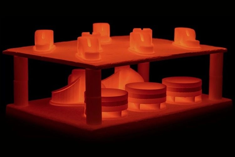
- Sintering: The “green” part is placed in an industrial furnace. There, the binder is first burned off and then the remaining metal particles a sintered together. The result is a fully metal part with dimensions that are about 20% smaller than the original “green” part. To compensate for this shrinkage, the parts are printed larger.
Today, sintering is used in the majority of the applications, as infiltration creates parts with inferior material properties and not well documented mechanical and thermal behavior.
Binder jetting & metal injection molding (MIM)
After sintering, binder jetting parts have very similar properties to parts manufactured with MIM. MIM is a manufacturing process that is used to mass-produce almost every small metal part found in consumer electronics or cars today.
MIM is a variation of the plastic injection molding process. Metal powder mixed in a plastic binder is injected into a mold to form the “green” part, which is then sintered to become metal.
So, metal binder jetting builds upon the know-how of the MIM process.
Benefits & limitations of metal binder jetting
Binder jetting is the only metal 3D printing technology today that can be used cost-effectively for low-to-medium batch production of metal parts.
Since no support structures are needed for printing, binder jetting systems can use their whole build volume. This allows it to compete in cost with traditional manufacturing, even for low-to-medium volume production.
Additionally, binder jetted parts have a smoother finish and sharper edges than DMLS/SLM, so extra finishing operations might not be necessary. Compared to DMLS/SLM, the cost of the raw metal powder is also lower, which plays a big role in the unit price.
On the other hand, parts produced with binder jetting will always have an internal porosity of about 0.2 to 2%. Note, that internal voids may not affect the tensile strength shown in the technical data sheets, but can greatly decrease the fatigue strength of a part.
Keep in mind that the sintering step is connected with significant part shrinkage. This shrinkage is non-homogenous and is difficult to predict with high precision. In practice, several trial prints are needed to end up with a CAD file that will produce the part with the desired final dimensions. The repeatability of the process is excellent though. This means that larger volumes of this part can be manufactured after successful calibration.
Technical characteristics of metal binder jetting
The table below summarizes the basic technical capabilities of a typical metal binder jetting 3D printer today. For additional design guidelines, jump to the design rules.
| Property | Metal Binder Jetting |
|---|---|
| Material selection | Currently limited Stainless steel, Tool steel, Tungsten Carbide |
| Dimensional accuracy | ± 0.2 mm (± 0.1 after trials) |
| Typical build size | 400 x 250 x 250 mm (-20% effective build size after sintering) |
| Common layer thickness | 35 - 50 μm |
| Typical surface roughness | RA 6 μm |
| Support | Not required for printing |
| Internal porosity | Between 0.2 - 2.0% |
| Cost per part | $$$ |
Part 4
Metal extrusion
Metal extrusion is an alternative, low-cost metal 3D printing process that is mainly suitable for prototyping purposes or for one-off custom parts.
Here, we examine in depth the characteristics and key benefits and limitations of this additive process to help you understand how to use it most effectively.
What is metal extrusion 3D printing?
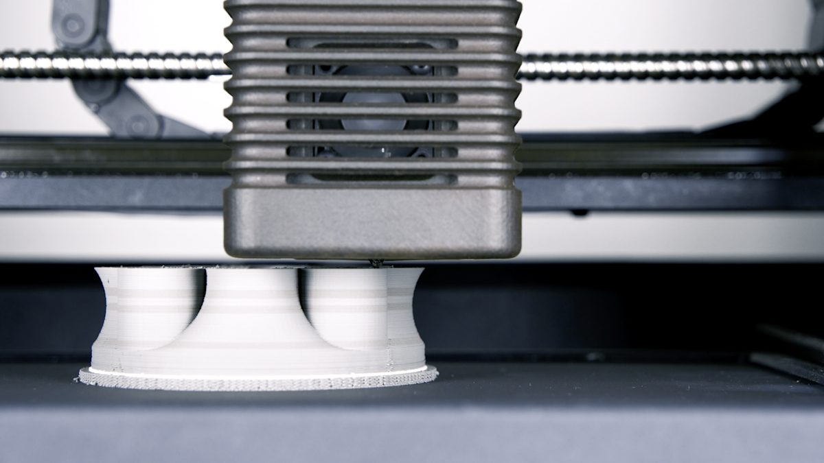
Metal Extrusion is a variation of the classic FDM process for plastics. The first Metal Extrusion 3D printers were released in 2018. The technology is also known under the names Bound Metal Deposition (BMD) or Atomic Diffusion Additive Manufacturing (ADAM)
Like FDM, a part is built layer-by-layer by extruding material through a nozzle. Unlike FDM, the material is not plastic, but a metal powder held together using a polymer binder. The result of the printing step is a “green” part of that needs to be-debinded and sintered to become fully metal.
How does metal extrusion work?
Metal extrusion is a three-stage process. It involves a printing step, a de-binding step, and a sintering step. Here’s how the printing step works:
- The raw material comes in a filament or rod form that typically consists of metal particles bound together by polymer and/or wax.
- This rod or filament is extruded through a heated nozzle and deposited layer-by-layer building a part based on the CAD model.
- At the same time, support structures are build if necessary. The interface between the support and the part is printed with a ceramic support material, which is easy to manually remove later.
When the print is complete, the resulting “green” part needs to be post-processed to become metal using similar steps as in Binder Jetting. The “green” is first washed in a solution for several hours to remove most of the binder. Then it is sintered in a furnace to bond the metal particles together and form a fully-metal part.
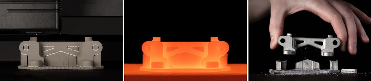
During sintering the part dimensions are reduced by about 20%. The parts are printed larger to compensate for this. Like in binder jetting, this shrinkage is not homogenous. This means that some trial and error is needed to produce accurate results for a particular design.
Metal extrusion vs. FDM of plastics
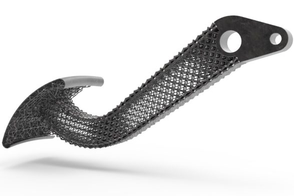
The way that metal extrusion and plastic FDM printers work is very similar. For example, both processes print parts hollow, using a cell outline and infill.
Apart from the material, there are two other important practical differences between metal extrusion and FDM that you should keep in mind. Both are connected to the mechanics of the de-binding and sintering process.
- Wall thickness: In metal extrusion, parts should always have a consistent wall thickness (preferably, smaller than 10 mm). If this is not the case, then the time needed to fully de-bind and sinter the parts can increase by several hours.
- Support structures: Like FDM, in metal extrusion supports are often required during printing. In metal extrusion, though, support is also needed for the sintering step. At these very high temperatures, the metal material becomes soft and pliable and may collapse under its own weight.
Benefits & limitations of metal extrusion
Metal extrusion is excellent for functional prototyping and small productions of metal parts that would otherwise require a 5-axis CNC machining to produce.
Coming at a fraction of the cost of DMLS/SLM or binder jetting, metal extrusion printers are the most economical metal system to date. This way, a wider audience can benefit from the key benefits of metal 3D printing (optimized structures, assembly consolidation, internal channels), especially for prototyping purposes and small production runs. Moreover, the ease-of-use of these systems and their low health and safety requirement make them appealing for in-house production of custom parts or tooling to support other operations.
When compared to other manufacturing technologies though (like CNC machining and sheet metal), the cost of metal extrusion is still considerable. For simple geometries, it is more economical (and usually faster) to choose a traditional manufacturing process, even when outsourcing production. The biggest contributor to this final cost is the time required to de-bind and sinter the as-printed “green” parts. It takes on average 24 to 72 hours to do so.
From a technical point of view, the parts produced with these systems are not suitable for demanding applications as they have lower mechanical properties than the wrought metal (~33% lower strength), due to their internal porosity (approximately 2-4%).
Technical characteristics of metal extrusion
The table below summarizes the basic technical capabilities of a typical metal extrusion 3D printer today. For additional design guidelines, jump to the design rules.
| Property | Metal Extrusion |
|---|---|
| Material selection | Currently very limited Stainless steel |
| Dimensional accuracy | ± 0.5 mm with a lower limit of ± 0.5 mm (± 0.020") |
| Typical build size | 300 x 200 x 200 mm (-20% effective build size after sintering) |
| Common layer thickness | 50 - 200 μmm |
| Support | Required for printing and sintering |
| Internal porosity | Between 2.0 - 4.0% |
| Cost per part | $$$ |
Part 5
Design for metal 3D printing
Designing for metal 3D printing requires a new mindset and comes with a unique set of design rules and best practices.
In this section, we introduce you to the basic principles and tools that will help you get the most out of your designs, such as topology optimization.
Key design considerations
Designing for an additive process follows a different set of rules than designing for “traditional” manufacturing. The unique design freedom, as well as the unique set of limitation, demand a shift in the mindset of the designer.
Here is a list of key ideas you should keep in mind while designing for metal 3D printing:
Key design consideration
Due to its high cost, it is rarely economically feasible to manufacture parts that have been designed for a traditional process using metal 3D printing.
Actually, it is often technically impossible to reproduce these geometries. For example, section thicker than 10 mm are prone to warping or other manufacturing defects and should be avoided.
Design complexity is often considered harmful, as it is connected to an increased cost. In metal 3D printing, this is not the case. On the contrary, finding a way to maximize the added value that geometric complexity brings to a system is key to take full advantage of the benefits of metal 3D printing.
When you begin to redesign a part or assembly for metal 3D printing, it is usually a good idea to start with a blank canvas. This way you can avoid being restricted by preconceived designs.
Clearly defining the design requirements (loads, boundary condition, part weight etc.) is key here. We will see in the next section that modern CAD software use these as input to create optimized structures with organic forms.
It is a good practice to have a clear vision of how the part will be orientated in the machine. Print orientation is important as it defines the position and need of support structures.
The aim of the designer should be to create parts with self-supporting features, minimizing the need for support and ensuring build success.
Independent of the process, post-processing is always required in metal 3D printing. This can be obligatory (such as support removal in DMLS/SLM or sintering in binder jetting and metal extrusion) or optional (such as CNC machining step to achieve tighter tolerances or a heat treatment to improve material properties).
So it is essential to keep the post-processing requirements and available option in your mind while designing a part for metal 3D printing.
Design optimization tools & software
Modern CAD packages offer tools to help you take full advantage of the geometric freedom of metal 3D printing. Using these algorithm-driven design tools, you can create organic-like structures that outperform parts that were designed using traditional methods.
There are three main strategies that can be used today. These strategies can either optimize the performance of an existing design or help in the creation of structures from scratch based on a set of design requirements.
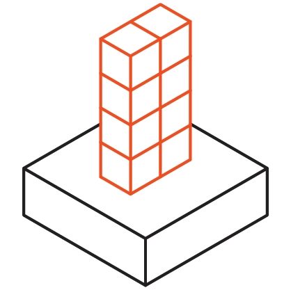
Lattice structures
Applying a lattice pattern is a great way to optimize an existing design.
Lattice structures can create lightweight parts, maximize the surface area of heat exchangers, or improve the printability and reduce the manufacturing cost of an existing design.
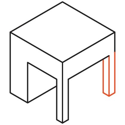
Topology optimization
Simulation-driven topology optimization aids in the creation of structures with minimal mass and maximal stiffness.
In topology optimization, the user-defined design space and the load cases are analyzed to determine the areas from which material can be removed. The result of the simulation can then be used to design parts for optimal performance for these loading scenarios.
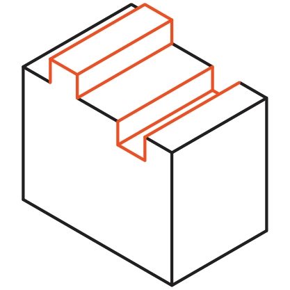
Generative design
Generative design is a variation of the simulation-driven topology optimization process.
In generative design, instead of a single output, the analysis produces multiple design candidates. The resulting designs are all manufacturable and fulfill the design requirements. This way, the designer can explore different solutions and select the one that fits the application (for example, based on secondary trade-offs).
It is highly recommended to use one of these advanced CAD techniques - especially when designing parts DMLS/SLM. Below we collected a short list of CAD packages that offer design optimization tools for metal 3D printing to get you started:
Design rules
Even when using advanced CAD tools, you must follow certain design guidelines. These have to do with the basic mechanics of the metal 3D printing processes. Here is a list of the most important design rules:
Minimum wall thickness
DMLS/SLM: 0.4 mm
Binder Jetting: 1.0 mm
Metal Extrusion: 1.0 mm
Binder jetting and metal extrusion parts in the “green” state are fragile. Thicker wall sections reduce the probabillity of breaking.

Maximum aspect ratio
DMLS/SLM: 8:1
Binder Jetting: 8:1
Metal Extrusion: 8:1
Extra stability can be added to tall features using support ribs (similar to injection molding).
Minimum feature size
DMLS/SLM: 0.6 mm
Binder Jetting: 2.0 mm
Metal Extrusion: 3.0 mm
Isolated features are more prone to failure during printing or handling than wall sections. For pins, consider using an off-the-self insert instead.
Minimum detail size
DMLS/SLM: 0.4 mm
Binder Jetting: 0.1 mm
Metal Extrusion: 0.5 mm
The minimum detail depends on the size of the laser, binder droplet or nozzle.
Minimum hole diameter
DMLS/SLM: Ø1.5 mm
Binder Jetting: Ø1.0 mm
Metal Extrusion: Ø1.5 mm
For holes that are not aligned along the build direction, consider using a teardrop shape instead to avoid the need for support.
Maximum overhang angle
DMLS/SLM: 50°
Binder Jetting: N/A
Metal Extrusion: 45°
Additional support might be necessary for sintering in binder jetting and metal extrusion.
Unsupported edges
DMLS/SLM: 0.5 mm
Binder Jetting: 20 mm
Metal Extrusion: 0.5 mm
Consider eliminating the overhang by adding a 45° chamfer under the unsupported edges.
Follow the links below to learn more about designing for the different metal 3D printing processes:
Part 6
Useful resources
In this guide we touched upon all you need to get you started with metal 3D printing, but there is plenty more to learn.
Below we list the best and most useful resources on metal 3D printing and other digital manufacturing technologies for those who want to delve deeper.
Knowledge Base
Here, we touched upon all you need to get you started with 3D printing. There is plenty more to learn though in our Knowledge Base – a collection of technical articles on all manufacturing technologies, written by experts from Protolabs Network and the manufacturing industry.
Here is a selection of our most popular articles on 3D printing:
Guides to other Manufacturing Technologies
Want to learn more about Digital Manufacturing? There are more technologies to explore:
Need metal 3D printed parts?
Go to Protolabs.com