To request a quote for custom CNC parts on the Protolabs Network platform, you only need to supply a 3D CAD file. Modern CNC machining systems can interpret the geometry of a part directly from CAD, which means that additional documentation, such as technical drawings, isn’t always required.
However, while technical drawings are not necessary to request a quote for CNC machining, they are still very important and widely used in manufacturing. Technical drawings improve the communication of technical requirements between designers, engineers and product developers and machinists. Providing a technical drawing can help you source better parts and even reduce your costs.
In this article, we’ll explain when to include a technical drawing (or machining blueprints) in your CNC order and what you need to include to get the most out of part sourcing. This article also includes technical drawing guidelines and best practices from our engineers.
Did you know we offer local sourcing for CNC machining?
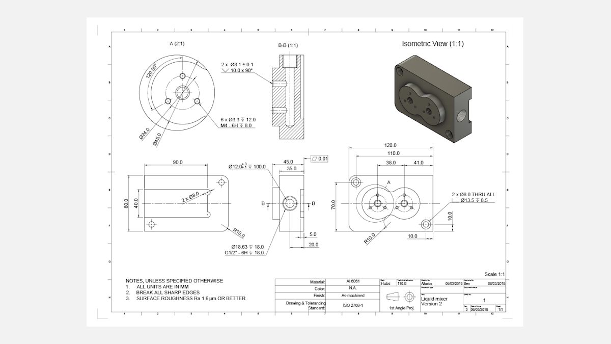
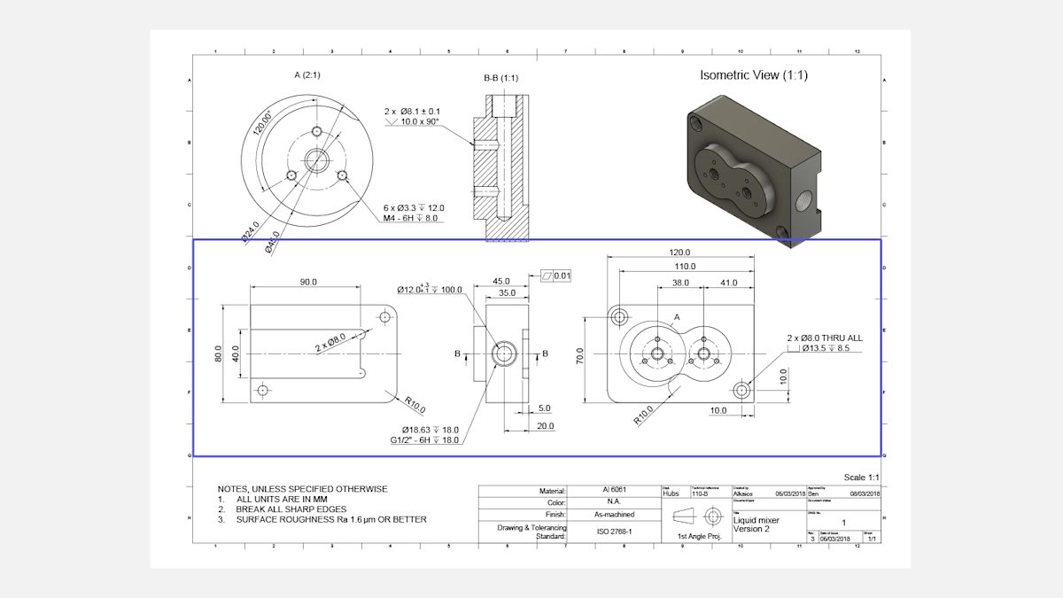
The image above is a well-designed, fully-dimensioned technical drawing and a useful example for getting the most out of this guide. Click here to download a high-resolution version of this technical drawing, and here to download the CAD file.
Have a CAD file and technical drawing ready to go for your custom part?
Why are technical drawings still important for sourcing parts?
While CAD files are quite comprehensive in what they can communicate to CNC machines, technical drawings still contain information that a 3D CAD file can’t convey. This includes:
-
Internal or external threads
-
Features with tolerances that exceed the standard
-
Individual surfaces with specific finishing requirements (surface roughness, for example)
Even if your design doesn’t include these features, it’s generally good practice to include a technical drawing along with your 3D CAD file when placing a CNC order. Usually, the 3D CAD file is used for programming the CNC machine, and the drawing is used as a reference throughout the machining process.
Most CNC service providers can also manufacture parts directly from these CNC turning and milling drawings. In some cases, we find that they ever prefer them over CAD files. This is because:
-
Some service providers are trained to quickly interpret the geometry of a part from a 2D drawing
-
It’s easier to identify the main dimensions, functions and critical features of a part from 2D blueprints
-
It’s easier to assess the cost of manufacturing the part
As you can see, technical drawings can be a significant part of sourcing custom parts, and there are many different standards and best practices for drafting them. If your drawing communicates all the technical requirements clearly, then it doesn’t matter which drafting techniques you use.
Pro tip from Protolabs Network
The model in the example drawing above is fully-dimensioned. While we recommend this, it’s not necessary, as the 3D CAD file conveys the basic dimensions. To save time, you can annotate the most important features that you want to be measured and the threads in your technical drawing.
What is the anatomy of a technical drawing?
A technical drawing typically consists of the following crucial components:
-
A title block
-
An isometric/pictorial view of the part
-
The main orthographic views of the part
-
Section views or detail views
-
Notes to the manufacturer
Title block
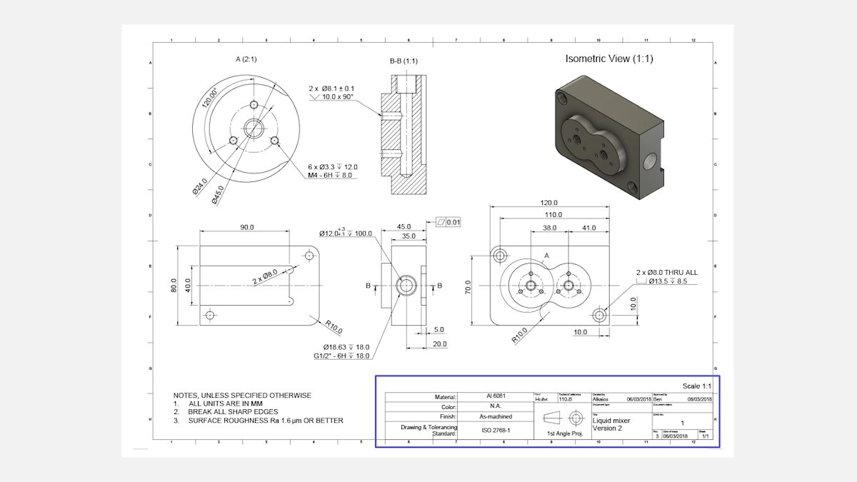
The title block contains basic information about the part you’re producing, such as the part name, the material, the finishing and color requirements, the designer's name and the company. It’s essential to fill in this basic information, as it informs the manufacturer about the part’s primary function.
The title block also contains other technical information, including the scale of the blueprint and the standards used for dimensioning and tolerancing.
Another element that’s usually present in or near the title block is the angle projection. The angle projection determines the way the views are arranged in the drawing. Typically, drawings that use ASME standards (US & Australia) use 3rd angle projection, and ISO/DIN standards (Europe) use 1st angle projection. The example blueprint at the beginning of this article uses ISO/DIN standards.
The pictorial (isometric) view
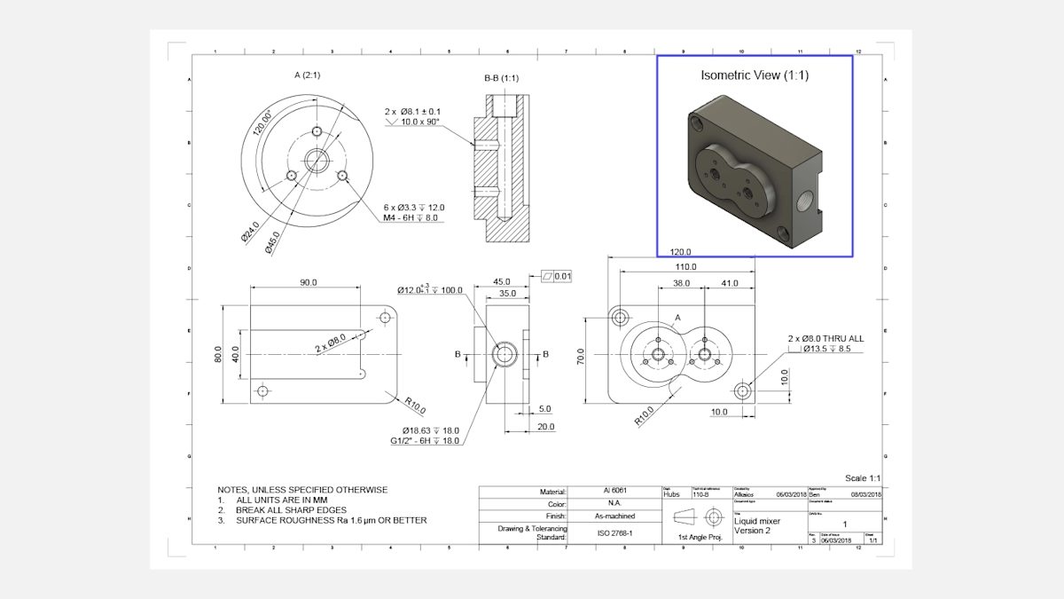
We advise that you add one or more 3D pictorial views of the part to your technical drawing. This makes the drawing easier to understand at a glance. Isometric views combine the illusion of depth with the undistorted presentation of your part’s geometry (vertical lines remain vertical and horizontal lines are drawn at 30 degrees).
The main orthographic views
Most information about the geometry of your part is conveyed in the main orthographic views.
These are two-dimensional depictions of the three-dimensional object, representing the exact shape of the part, as seen from the outer side of a bounding box one side at a time. Only the edges of the parts are drawn this way to communicate dimensions and features more clearly.
For most parts, two or three orthographic views are sufficient to accurately describe the whole geometry.
Section views

Section views can be used to show the internal details of a part. The cutting line in a main orthographic view shows where the part is cross-sectioned and the cross-hatch pattern of the section view indicates regions where raw material has been removed.
Technical drawings can have multiple section views with two letters linking each cutting line with each section view (for example A-A, B-B and so on). The arrows of the cutting line indicate the direction.
Usually, section views are placed in line with an orthographic view, but they can also be placed elsewhere in the drawing if there is not enough space. The part can be sectioned along its whole width (like in the example above), along half its width, or at an angle.
Pro tip from Protolabs Network
Remember that the edges of hidden internal features can also be represented in an orthographic using dashed lines, but section views add more clarity.
Detailed views
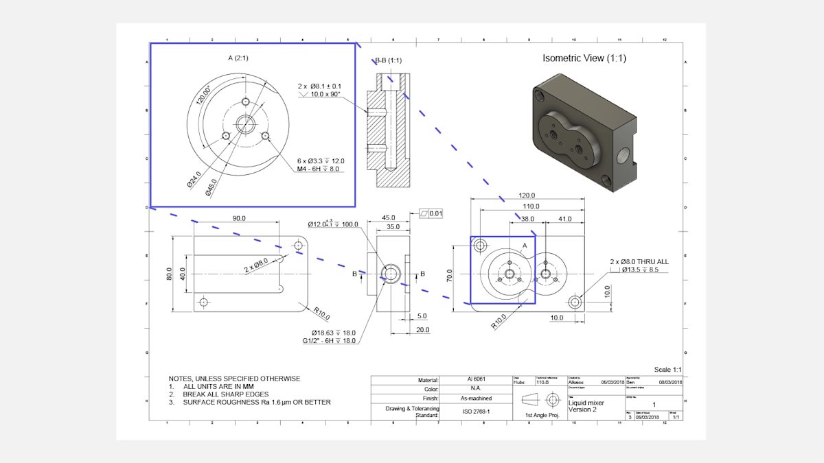
Detailed views are used to highlight complex or difficult-to-dimension areas of a main orthographic view. They are typically circular in shape (placed offset to avoid confusion) and are annotated with a single letter that links the detail view with the main drawing (for example A, B and so on).
Detail views can be placed anywhere on the drawing and can use a different scale than the rest of the drawing, as long as this is clearly communicated (like in the example above).
What are notes to the manufacturer and why do you need them?
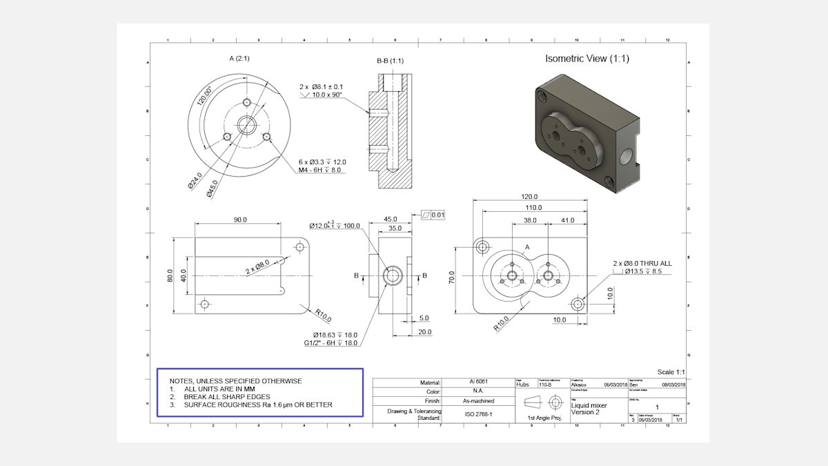
Adding notes to the manufacturer on the technical drawing is very important, though not required for getting a quote. They convey additional information that was not included in the blueprints themselves.
These seemingly extra but vital bits of information include instructions to break (deburr) all sharp edges and specific overall surface finishing requirements. You can also use this section of the drawing to reference another CAD file or another component with which the part in the drawing interacts.
Notes to the manufacturer often use symbols instead of text. For example, surface roughness is commonly annotated with a symbol.
Pro tip from Protolabs Network
If only one surface requires a specific surface roughness finish, then it should be annotated on the drawing and not on the notes. The standard surface roughness of the parts machined on Protolabs Network is Ra 3.2 μm (125 μinch). Finishes to a surface roughness of Ra 1.6 μm (64 μinch) and 0.8 μm (32 μinch) are also available.
How to prepare a technical drawing in 7 simple steps
When drafting your technical drawing, we recommend the following 7 steps to prepare the best possible blueprints.
Step 1
Define the most important views and place the relevant orthographic in the center of the drawing, leaving enough space between them to add dimensions.
Step 2
If your part has internal features or complex and difficult-to-dimension areas, consider adding section views or detail views.
Step 3
Add construction lines to all views. Construction lines include centerlines (to define planes or axes of symmetry), center marks, and center mark patterns (to define the location of the center of holes or of circular patterns).
Step 4
Add dimensions to your CNC drawing, starting with the most important dimensions first (we give more tips on this in the next section).
Step 5
Specify the location, size and length of all threads.
Step 6
Add tolerances to features that need higher accuracy than the standard tolerance. We follow ISO 2768, -medium or -fine for metals and -medium for plastics.
Step 7
Fill in the title block and make sure that all relevant information and requirements that exceed the standard practices (surface finish and deburring, for instance) are mentioned in the additional notes. When your drawing is ready, export it as a PDF file and attach it to your order in the quote builder.
Now that you are familiar with the basic structure of a technical drawing, let's delve deeper into the specifics of adding dimensions, annotations and tolerances.
Curious about the cost of CNC machining?
How do you add critical dimensions to technical drawings?
If you include both a 3D CAD file and a technical drawing in your order, the manufacturer will primarily check the dimensions of the technical drawing. We recommend that you dimension all important features on your drawings thoroughly to avoid errors once the part is in production.
We recommend fully dimensioning your technical drawing to avoid errors in the manufacturing process. However, you can save time by dimensioning only the features you want the CNC machining service provider to measure.
Here are some tips to help you dimension your models:
-
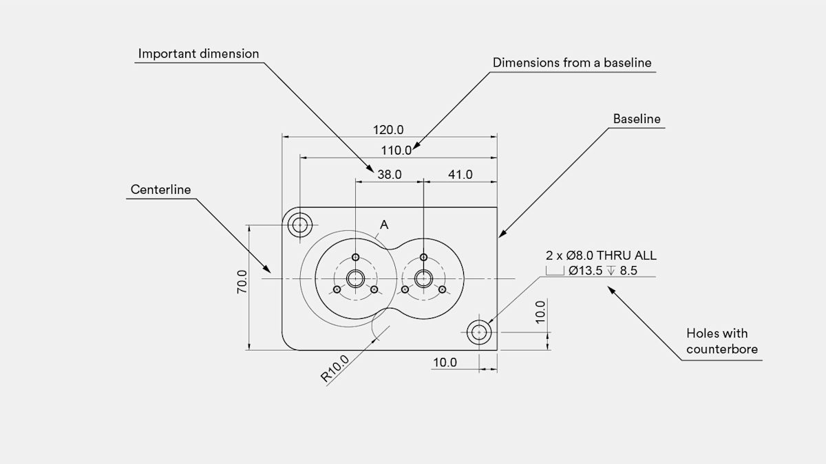
Start by placing the overall dimensions of the part.
-
Next, add the dimensions that are most critical for functional purposes. For example, the distance between the two holes in the example drawing is vital.
-
Then, add dimensions to other features. A good practice is to place all dimensions starting from the same baseline (also known as datum), as shown in the example.
-
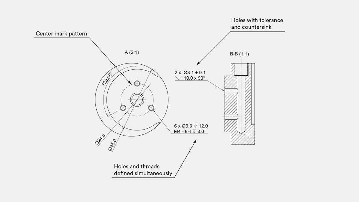
The dimensions should be placed on the view that describes the feature most clearly. For example, the dimensions of the threaded holes are not included in this view, as they are more clearly described in the detailed view.
-
For repeated features, add dimensions to only one of them, indicating the total number of times the feature is repeated on the current view. In the example, two identical holes with a counterbore are specified using a 2x in the callout.
Want to explore the topic of adding dimensions to your drawing in even more depth? Check out this nifty article from MIT.
How do you add hole callouts to a technical drawing?
Holes are common features in CNC machined parts. They are usually machined with a drill so they have standardized dimensions.
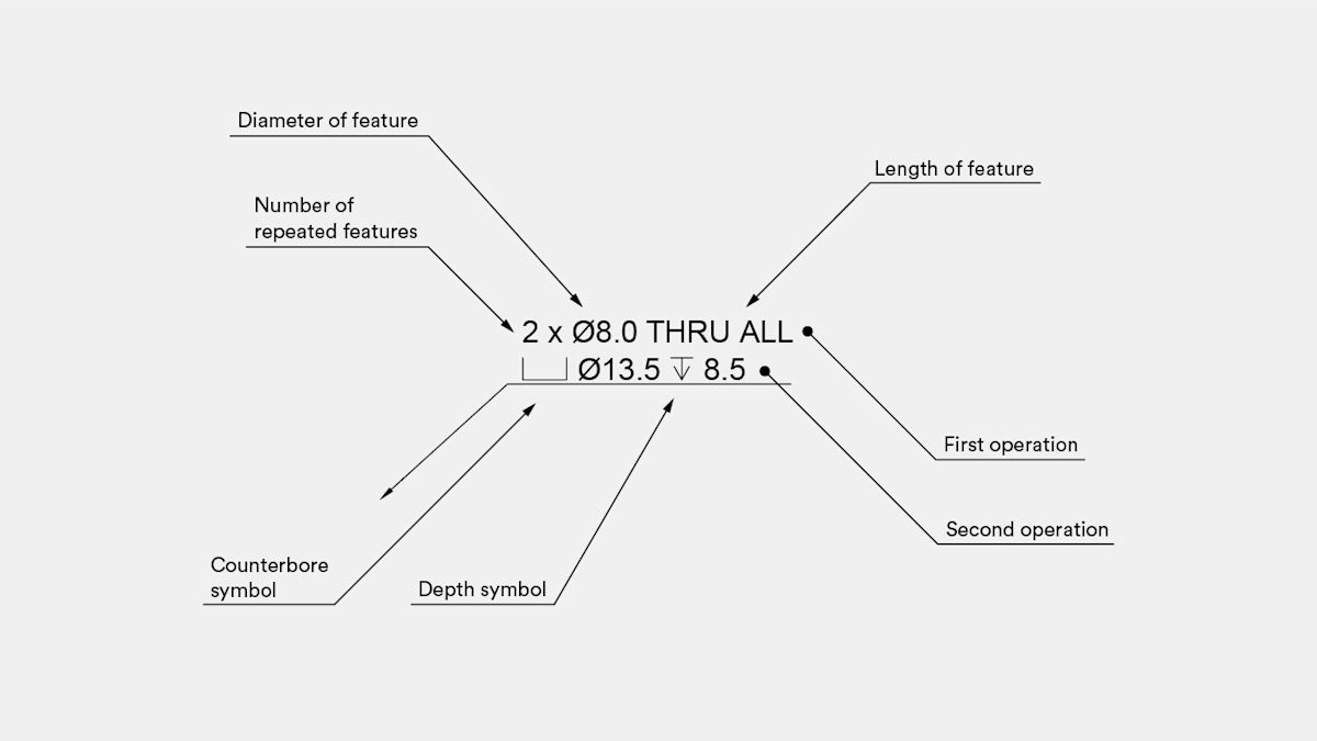
They often also include secondary features, such as counterbores (⌴) and countersinks (⌵). Adding a callout instead of dimensioning each individual feature is recommended.
In the example below, the callout defines two identical through holes with a counterbore. The depth symbol (↧) can be used instead of adding an additional dimension to the drawing.
How do you add threads to a technical drawing?
If your parts contain threads, then you must clearly identify and define them on the technical drawing. Threads should be defined by indicating a standard thread size (for example M4x0.7) instead of a diameter dimension. We recommend providing detailed thread callouts, as they add clarity to the drawing and allow the specification of pilot holes and threads with different lengths.
In this case, the first operation should define the dimensions of the pilot hole (the appropriate diameter can be found in standard tables), and the second operation the dimension (and tolerance) of the thread.
Pro tip from Protolabs Network
Always add a "cosmetic" thread to your 3D CAD files instead of a "modeled" thread.
How do you specify tolerances in a technical drawing?

Tolerances define a range of acceptable values for a certain dimension of a part. Tolerances tell a story about the function of the part and are especially important for features that interact with other components.
Tolerances come in many different formats and can be applied to any dimension on a CNC drawing (both linear or angular).
Bilateral tolerances, the simplest tolerance, are symmetrical around the base dimension (for example, ± 0.1 mm). There are also unilateral tolerances (with different upper and lower limits) and engineering fit tolerances, which are defined in the technical table (for example, 6H). A flatness tolerance (⏥) was defined in the example above.
Pro tips from Protolabs Network
Tolerances are only required on a technical drawing when they have to exceed the standard value for optimal part functionality. We follow ISO 2768, -medium or -fine for metals and -medium for plastics.
A more advanced way to define tolerances is GD&T (Geometric Dimensioning & Tolerancing).
What is Geometric Dimensioning & Tolerancing (GD&T)?
The Geometric Dimensioning & Tolerancing (GD&T) system is more difficult to apply than standard dimensioning and tolerancing but is considered superior, as GD&T communicates engineering intent more clearly. With GD&T, you can define looser tolerances and still fulfill the main design requirements, while improving quality and reducing cost.
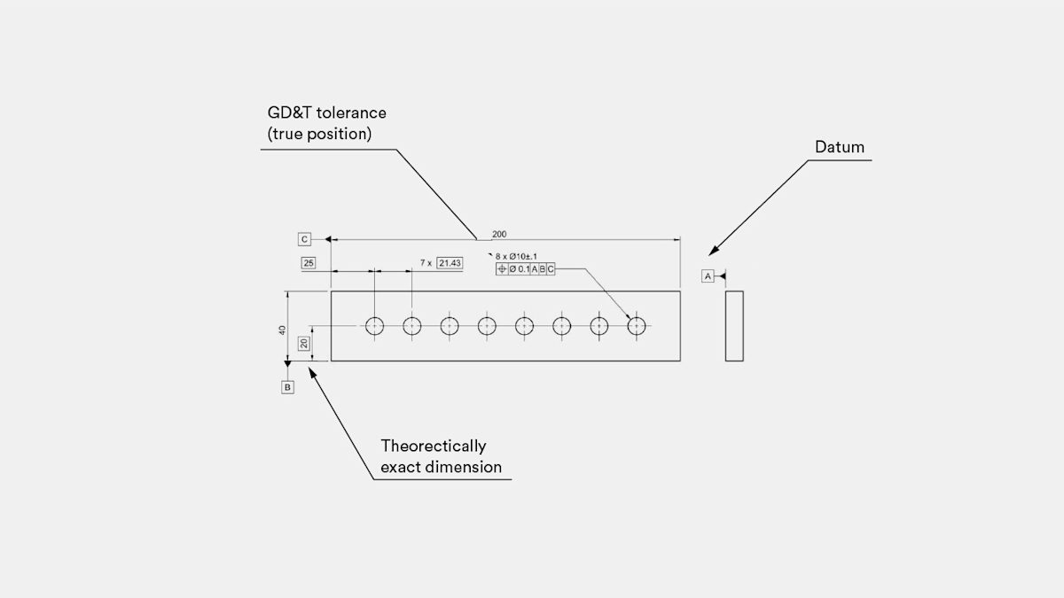
In the above example, true position (⌖) was used to define the tolerance of this pattern of holes. Other common geometric tolerances include flatness (⏥) and concentricity (◎).
Here is an example of how to apply the GD&T system to a part design:
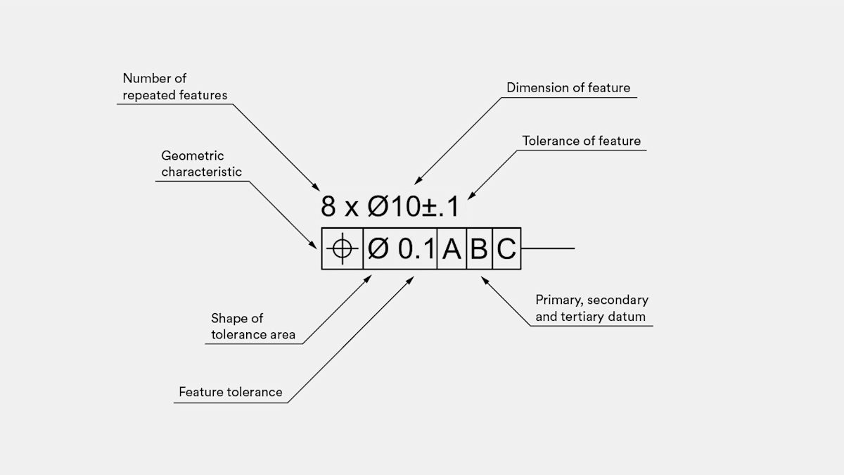
This callout defines eight holes with a nominal diameter of 10 mm and a tolerance of ± 0.1 mm to their diameter. This means that no matter where you measure this diameter, the result of the measurement must be between 9.9 and 10.1 mm.
The true position tolerance defines the location of the center of the hole with respect to the three main baseline edges (datum) of the part. This means that the center axis of the hole must always be within an ideal cylinder that has a center at the location defined by the theoretically exact dimensions in the drawing and a diameter equal to 0.1 mm.
This practically means that the center of the hole will not drift away from its designed location, guaranteeing that the part can fit the rest of the assembly.
We recommend adding GD&T information to your parts for critical assemblies and at later stages of the design process (for example, during full-scale production). These both have higher metrology requirements, which increase the cost of a one-off prototype.
Don't have a technical drawing yet? You can still get an instant quote
Frequently asked questions
Do I need a technical drawing for CNC machining?
While technical drawings aren't used for obtaining g-code, they are vital for quality control. Technical drawings are also essential when your part contains threads, tolerances and/or finishes on specific surfaces.
What does a technical drawing have to include?
A standard technical drawing has to include essential information like a title bar, views of the parts—including the orthogonal view, cross-sectional view and isometric view—coordinate details, all requirements and any additional annotations. Most importantly, make sure the title block does not contradict the information in the CAD file you've uploaded to the quote builder.
Do technical drawings need notes to the manufacturer?
Notes to the manufacturer are not technically mandatory, but adding them to your technical drawing can be crucial for conveying information that wouldn’t fit in the blueprints themselves.
How do I add a technical drawing to the quote builder?
You can easily upload a PDF of your technical drawing in the part specifications section of the quote builder by clicking “Upload attachment.” Please note that your CAD file and part specifications selected in the checkout will take priority over your technical drawings. For more information, head to the Help Center.